286
2467S–AVR–07/09
ATmega128
Memory
Programming
Program and Data
Memory Lock Bits
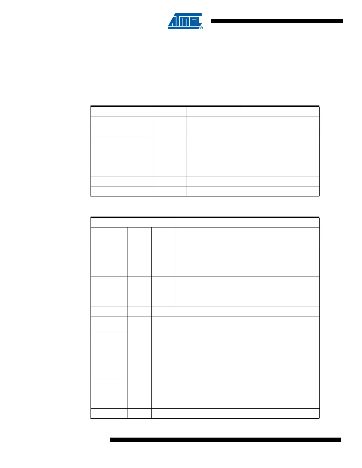
The ATmega128 provides six Lock bits which can be left unprogrammed (“1”) or can be pro-
grammed (“0”) to obtain the additional features listed in Table 116. The Lock bits can only be
erased to “1” with the Chip Erase command.
Note: “1” means unprogrammed, “0´means programmed
Table 115. Lock Bit Byte
Lock Bit Byte Bit No. Description Default Value
7 – 1 (unprogrammed)
6 – 1 (unprogrammed)
BLB12 5 Boot lock bit 1 (unprogrammed)
BLB11 4 Boot lock bit 1 (unprogrammed)
BLB02 3 Boot lock bit 1 (unprogrammed)
BLB01 2 Boot lock bit 1 (unprogrammed)
LB2 1 Lock bit 1 (unprogrammed)
LB1 0 Lock bit 1 (unprogrammed)
Table 116. Lock Bit Protection Modes
Memory Lock Bits Protection Type
LB mode LB2 LB1
1 1 1 No memory lock features enabled.
210
Further programming of the Flash and EEPROM is
disabled in Parallel and SPI/JTAG Serial Programming
mode. The Fuse bits are locked in both Serial and Parallel
Programming mode.
(1)
300
Further programming and verification of the Flash and
EEPROM is disabled in Parallel and SPI/JTAG Serial
Programming mode. The Fuse bits are locked in both
Serial and Parallel Programming mode.
(1)
BLB0 mode BLB02 BLB01
111
No restrictions for SPM or (E)LPM accessing the
Application section.
2 1 0 SPM is not allowed to write to the Application section.
300
SPM is not allowed to write to the Application section, and
(E)LPM executing from the Boot Loader section is not
allowed to read from the Application section. If interrupt
vectors are placed in the Boot Loader section, interrupts
are disabled while executing from the Application section.
401
(E)LPM executing from the Boot Loader section is not
allowed to read from the Application section. If interrupt
vectors are placed in the Boot Loader section, interrupts
are disabled while executing from the Application section.
BLB1 mode BLB12 BLB11