91
2467S–AVR–07/09
ATmega128
Note: 1. n = 3, 2, 1or 0.
When changing the ISCn1/ISCn0 bits, the interrupt must be disabled by clearing its Interrupt
Enable bit in the EIMSK Register. Otherwise an interrupt can occur when the bits are changed.
External Interrupt
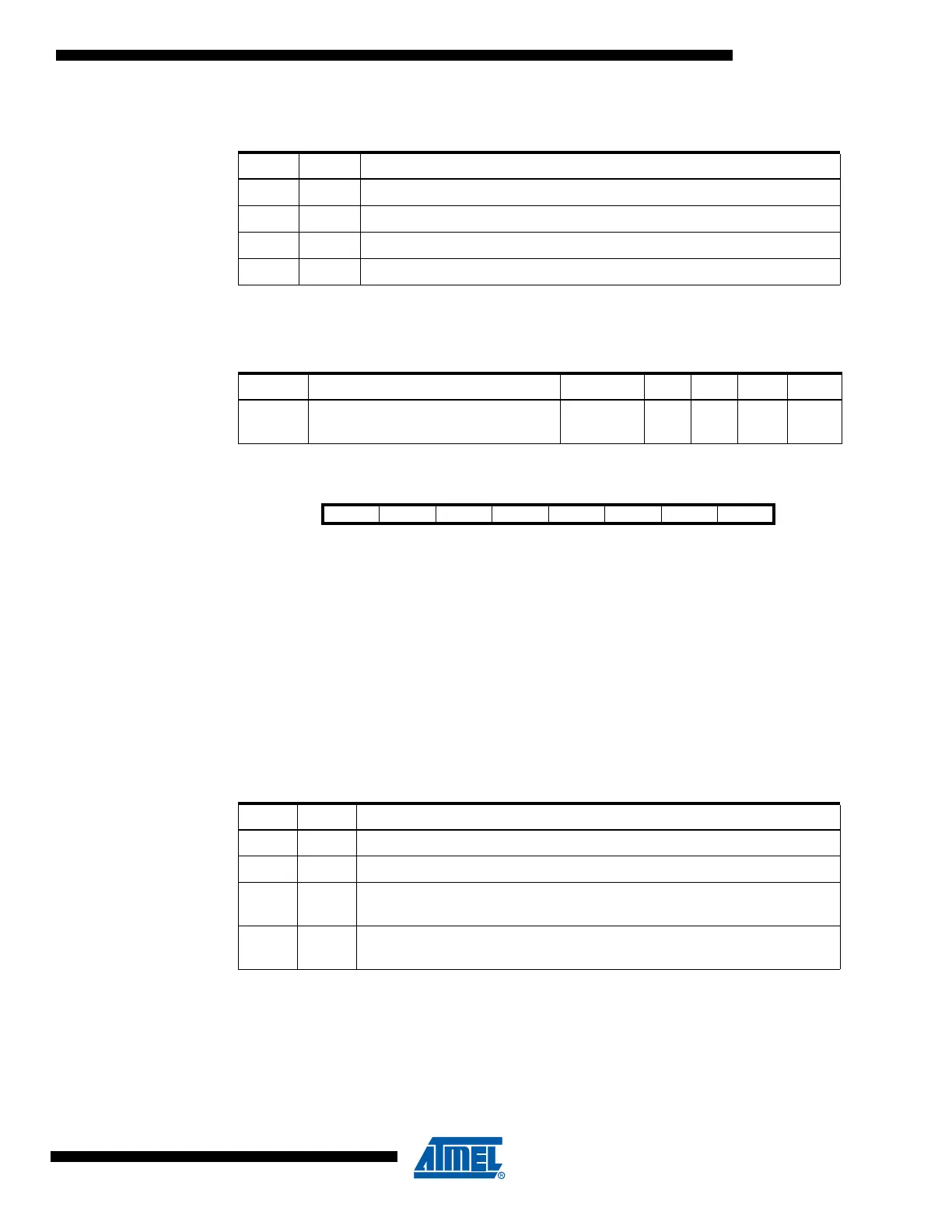
Control Register B –
EICRB
• Bits 7..0 – ISC71, ISC70 - ISC41, ISC40: External Interrupt 7 - 4 Sense Control Bits
The External Interrupts 7 - 4 are activated by the external pins INT7:4 if the SREG I-flag and the
corresponding interrupt mask in the EIMSK is set. The level and edges on the external pins that
activate the interrupts are defined in Table 50. The value on the INT7:4 pins are sampled before
detecting edges. If edge or toggle interrupt is selected, pulses that last longer than one clock
period will generate an interrupt. Shorter pulses are not guaranteed to generate an interrupt.
Observe that CPU clock frequency can be lower than the XTAL frequency if the XTAL divider is
enabled. If low level interrupt is selected, the low level must be held until the completion of the
currently executing instruction to generate an interrupt. If enabled, a level triggered interrupt will
generate an interrupt request as long as the pin is held low.
Note: 1. n = 7, 6, 5 or 4.
When changing the ISCn1/ISCn0 bits, the interrupt must be disabled by clearing its Interrupt
Enable bit in the EIMSK Register. Otherwise an interrupt can occur when the bits are changed.
Table 48. Interrupt Sense Control
(1)
ISCn1 ISCn0 Description
0 0 The low level of INTn generates an interrupt request.
01Reserved
1 0 The falling edge of INTn generates asynchronously an interrupt request.
1 1 The rising edge of INTn generates asynchronously an interrupt request.
Table 49. Asynchronous External Interrupt Characteristics
Symbol Parameter Condition Min Typ Max Units
t
INT
Minimum pulse width for
asynchronous external interrupt
50 ns
Bit 76543210
ISC71 ISC70 ISC61 ISC60 ISC51 ISC50 ISC41 ISC40 EICRB
Read/Write R/W R/W R/W R/W R/W R/W R/W R/W
Initial Value00000000
Table 50. Interrupt Sense Control
(1)
ISCn1 ISCn0 Description
0 0 The low level of INTn generates an interrupt request.
0 1 Any logical change on INTn generates an interrupt request
10
The falling edge between two samples of INTn generates an interrupt
request.
11
The rising edge between two samples of INTn generates an interrupt
request.