54
2467S–AVR–07/09
ATmega128
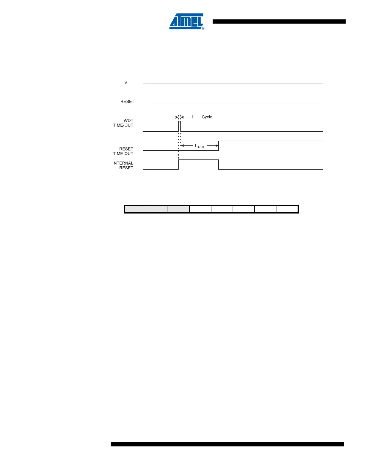
Watchdog Reset When the Watchdog times out, it will generate a short reset pulse of 1 CK cycle duration. On the
falling edge of this pulse, the delay timer starts counting the Time-out period t
TOUT
. Refer to page
55 for details on operation of the Watchdog Timer.
Figure 27. Watchdog Reset During Operation
MCU Control and
Status Register –
MCUCSR
The MCU Control and Status Register provides information on which reset source caused an
MCU reset.
Note that only EXTRF and PORF are available in ATmega103 compatibility mode.
• Bit 4 – JTRF: JTAG Reset Flag
This bit is set if a reset is being caused by a logic one in the JTAG Reset Register selected by
the JTAG instruction AVR_RESET. This bit is reset by a Power-on Reset, or by writing a logic
zero to the flag.
• Bit 3 – WDRF: Watchdog Reset Flag
This bit is set if a Watchdog Reset occurs. The bit is reset by a Power-on Reset, or by writing a
logic zero to the flag.
• Bit 2 – BORF: Brown-out Reset Flag
This bit is set if a Brown-out Reset occurs. The bit is reset by a Power-on Reset, or by writing a
logic zero to the flag.
• Bit 1 – EXTRF: External Reset Flag
This bit is set if an External Reset occurs. The bit is reset by a Power-on Reset, or by writing a
logic zero to the flag.
• Bit 0 – PORF: Power-On Reset Flag
This bit is set if a Power-on Reset occurs. The bit is reset only by writing a logic zero to the flag.
To make use of the reset flags to identify a reset condition, the user should read and then reset
the MCUCSR as early as possible in the program. If the register is cleared before another reset
occurs, the source of the reset can be found by examining the reset flags.
Internal Voltage
Reference
ATmega128 features an internal bandgap reference. This reference is used for Brown-out
Detection, and it can be used as an input to the Analog Comparator or the ADC. The 2.56V ref-
erence to the ADC is generated from the internal bandgap reference.
Bit 76543210
JTD – – JTRF WDRF BORF EXTRF PORF MCUCSR
Read/Write R/W R R R/W R/W R/W R/W R/W
Initial Value 0 0 0 See Bit Description