198
2467S–AVR–07/09
ATmega128
Two-wire Serial
Interface
Features • Simple yet Powerful and Flexible Communication Interface, only Two Bus Lines Needed
• Both Master and Slave Operation Supported
• Device can Operate as Transmitter or Receiver
• 7-bit Address Space allows up to 128 Different Slave Addresses
• Multi-master Arbitration Support
• Up to 400 kHz Data Transfer Speed
• Slew-rate Limited Output Drivers
• Noise Suppression Circuitry Rejects Spikes on Bus Lines
• Fully Programmable Slave Address with General Call Support
• Address Recognition Causes Wake-up when AVR is in Sleep Mode
Two-wire Serial
Interface Bus
Definition
The Two-wire Serial Interface (TWI) is ideally suited for typical microcontroller applications. The
TWI protocol allows the systems designer to interconnect up to 128 different devices using only
two bi-directional bus lines, one for clock (SCL) and one for data (SDA). The only external hard-
ware needed to implement the bus is a single pull-up resistor for each of the TWI bus lines. All
devices connected to the bus have individual addresses, and mechanisms for resolving bus
contention are inherent in the TWI protocol.
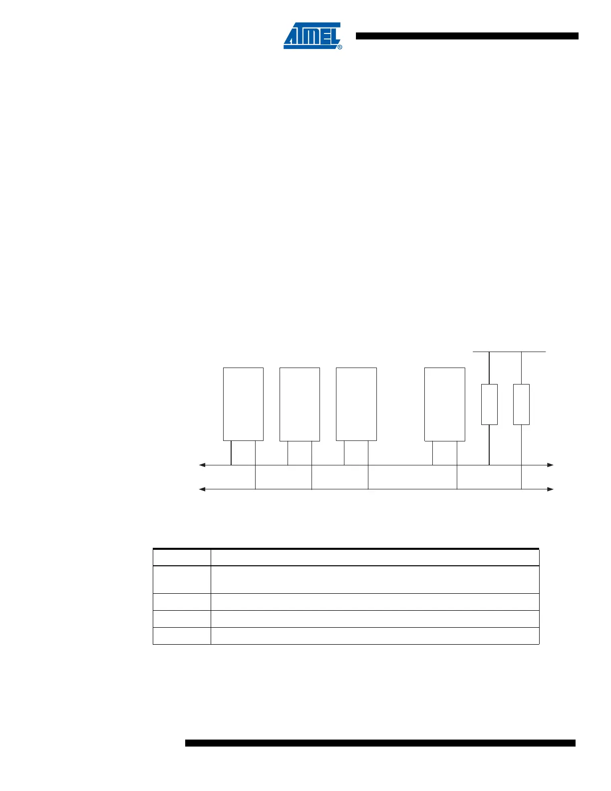
Figure 86. TWI Bus Interconnection
TWI Terminology The following definitions are frequently encountered in this section.
Electrical
Interconnection
As depicted in Figure 86, both bus lines are connected to the positive supply voltage through
pull-up resistors. The bus drivers of all TWI-compliant devices are open-drain or open-collector.
This implements a wired-AND function which is essential to the operation of the interface. A low
level on a TWI bus line is generated when one or more TWI devices output a zero. A high level
is output when all TWI devices tri-state their outputs, allowing the pull-up resistors to pull the line
Device 1
Device 2
Device 3
Device n
SDA
SCL
........
R1 R2
V
CC
Table 86. TWI Terminology
Term Description
Master The device that initiates and terminates a transmission. The master also
generates the SCL clock
Slave The device addressed by a master
Transmitter The device placing data on the bus
Receiver The device reading data from the bus