T1689 Technical Manual Rev 07 CDM Assembly
MV3000 Air Cooled DELTA Fitting a.c. Sharing Reactors
Page 117
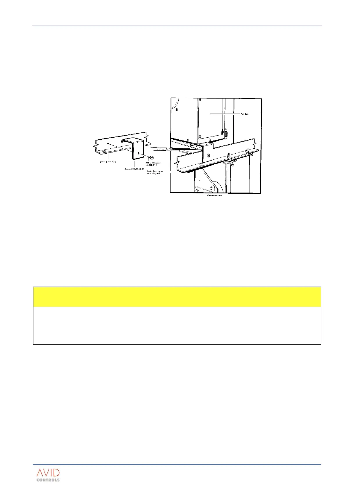
5.5.3 Fan Support Bracket
NOTE: The bracket (50Y9743/01) must be fitted to the cubicle to provide support for the high performance fan.
Failure to fit this bracket may cause mechanical damage.
Each bracket should be secured to the Upper Rear Cross Member with an M5 x 10 mm pozi-headed Taptite
screw.
Figure 5-5 shows the recommended fitting for the support bracket.
Figure 5-5. – Fitting of Fan Support Bracket (50Y9743/01)
5.6 FITTING A.C. SHARING REACTORS
The a.c. sharing reactors are usually mounted above or below the DELTA power modules. The mounting
frames for DELTA modules do not provide features for mounting the sharing reactors. Such mounting features
have to be provided by the CDM designer. Refer to Section 2: Specification for technical details, including
weight, and Appendix A: Dimensioned Mechanical Drawingsfor dimensional details.
5.7 FITTING DELTA POWER MODULES
• The modules are delicate and vulnerable to damage – handle carefully.
Only lift or move them by use of the lifting point.
Lay them down on the plain left-hand face when not fitted in a frame.
Do not leave modules unsupported in the upright position.
5.7.1 Guidance for Handling
The DELTA power modules require particular care and attention during handling to ensure that personnel are
not injured, or the modules damaged. The lifting arrangement is the same for each type of module.
They should only be lifted with a crane rated for the module weights, as detailed in Section 2: Specification, and
suitable for enclosure access. The modules should be handled without any cables or busbars attached. All
preparatory work should be done in the enclosure prior to any module being lifted.
5.7.2 Transistor Module Identity
DELTA transistor modules in the drive are numbered from 1 to 6. This identity is determined by the
connections that are made to the controller, see Appendix B: Electrical Connection Diagrams. It is
recommended that DELTA transistor module number 1 is located either at the left-hand or right-hand end of
the group of DELTA transistor modules in the cabinet. The remaining DELTA transistor modules should be
connected sequentially.