T1689 Technical Manual Rev 07 Specification
MV3000 Air Cooled DELTA MV3000e Controller
Page 25
2.4 MV3000E CONTROLLER
Units covered: MVC3001-400x.
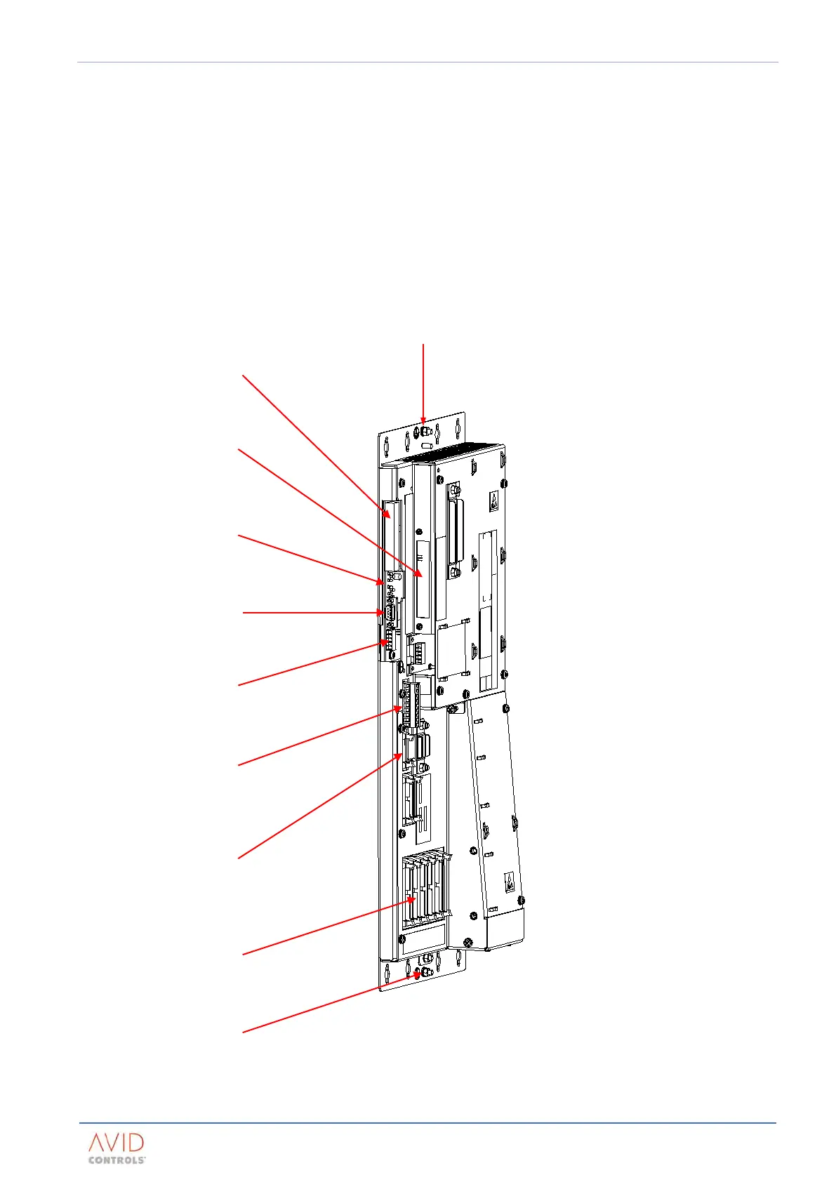
The MV3000e controller, shown in Figure 2–1, provides all control and monitoring functions for the transistor
and rectifier bridges in a DELTA drive (to a maximum of 6 transistor modules and 2 rectifier modules).
The controller is supplied in a ‘stand-alone’ chassis for mounting within an enclosure.
The controller derives an electrical supply from the SMPS of an associated DELTA transistor module. The
controller includes facilities for communication with both the transistor and rectifier bridge modules, and
external equipment.
The controller can be mounted at various locations in an enclosure. Section 3 Drive (CDM) Design includes the
requirements for determining the position of a controller in an enclosure.
Figure 2–1. – MVC3001-400x Controller Electrical Connections
PL20 – 50 way ribbon cable
connector for user I/O
termination panel
See Figure 8–
PL12 – rectifier control wiring
Optional communication
module slot
commu
PL10 – 16 way ribbon cable
connector for MVM
PL2 to PL7 – 40 way ribbon
cable connectors f