Specification T1689 Technical Manual Rev 07
MV3000e Controller MV3000 Air Cooled DELTA
Page 26
2.4.1 Electrical Connections
The connections from the MV3000e controller to other equipment in a DELTA drive are as follows:
• Six 40 way ribbon cable connectors for transistor modules, see Table 2–10;
• One 50 Way ribbon cable connector for a user I/O termination panel;
• One 16 way ribbon cable connector for an Mains Voltage Monitor unit;
• One D-type connector for a Drive Data Manager keypad;
• One 9 way connector for wiring to the rectifier module, see Table 2–11;
• One 5 way connector for wiring CANopen communications, see Table 2–12.
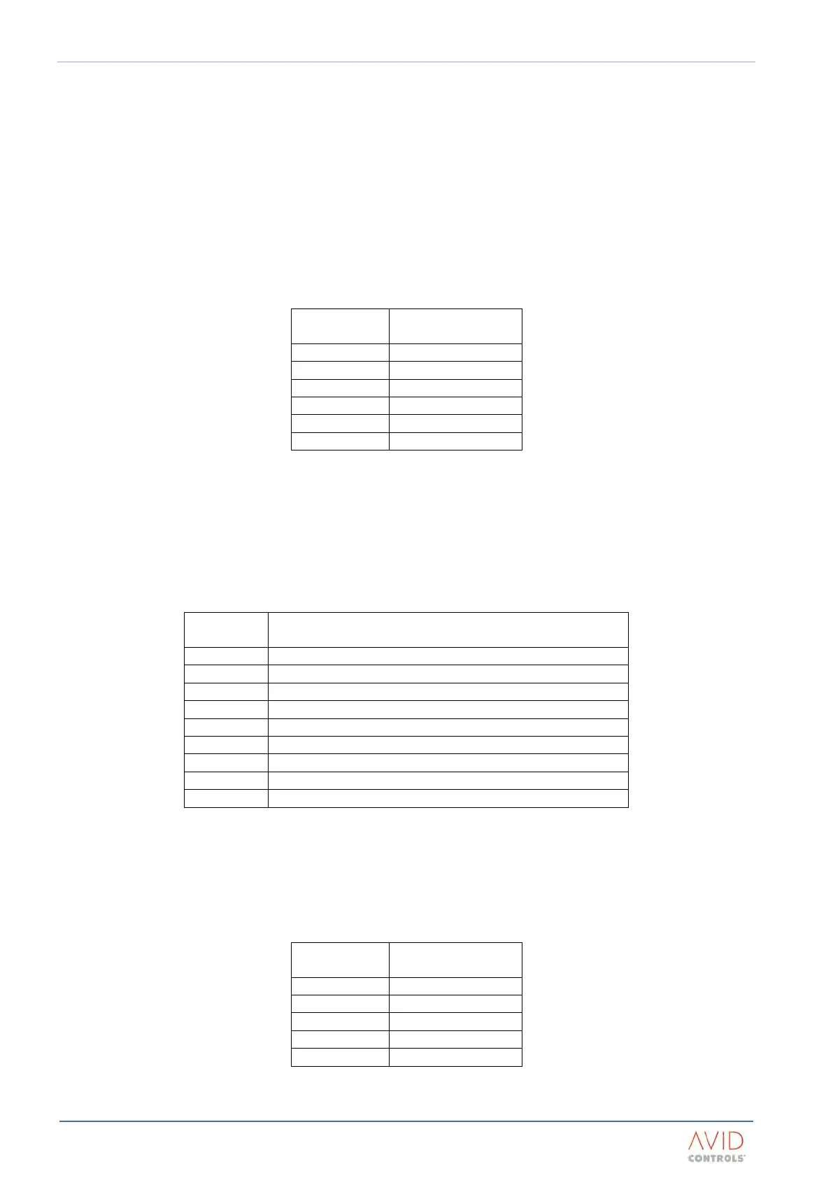
PL2 to PL7 carry the control signals to and from the DELTA transistor modules. Each DELTA transistor module is
identified by the connector position it occupies, as shown in Table 2–10:
Table 2–10. – DELTA Ribbon Connector Identities
The connection arrangement for the modules at the controller is shown in the connection diagrams in
Appendix B: Electrical Connection Diagrams.
The rectifier module control connections are made to PL12, as listed in Table 2–11. Rectifier control wiring
should have a cross sectional area between limits of:
Minimum 0.5 mm
2
or 20 AWG (use a consolidating crimp)
Maximum 2.5 mm
2
or 14 AWG
NTC Temperature Monitor - Thermistor
NTC Temperature Monitor - Thermistor
Thermostat (+24 V = HEALTHY)
Pre-charge Acknowledge (+24 V = HEALTHY)
Table 2–11. – PL12 Connection Functions For Rectifier Modules
CAN communications are made available on TB7. The pin assignments are shown in Table 2–12. The CAN port
connector wiring should have a cross sectional area between limits of:
Minimum 0.25 mm
2
or 23 AWG (use a consolidating crimp)
Maximum 1.5 mm
2
or 16 AWG
Table 2–12. – TB7 Connection Functions For The CANport