T1689 Technical Manual Rev 07 Specification
MV3000 Air Cooled DELTA DELTA Transistor Module
Page 57
2.10.8 Thermal Protection
Thermal protection is provided on DELTA transistor modules by a thermistor embedded within each IGBT
module, which is monitored by the MV3000e controller via the DIB.
2.10.9 Electrical Connections
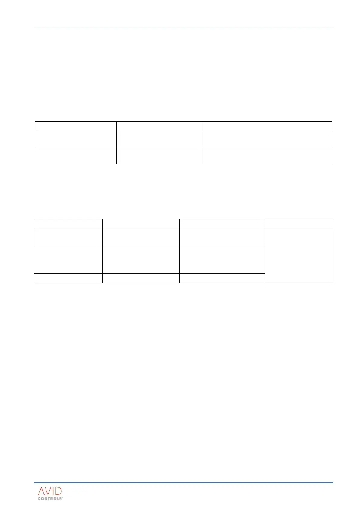
2.10.9.1 Control Connections
The control terminations for the DELTA transistor module are detailed in Table 2–28. The connectors are
supplied with the product.
SMPS supply / d.c. feedback 3-way Amp ‘Mat-n-lok’
Connector ‘TB1’ for SMPS & Voltage monitoring
(Pin 1 = DC+, 2=n/c, 3=DC-)
Control signals 2x 40-way Ribbon Connector
PCB connector PL3 (from the MV3000 SMPS)
PCB connector PL1 (to/from MV3000e Controller)
Table 2–28. – Terminations For Control Circuits On DELTA Transistor Modules
2.10.9.2 Power Connections
Terminations for 3-phase, d.c. outputs and earth/ground are detailed in Table 2–29.
a.c. terminals 1 x M10 stud per phase 120mm
2
(250 MCM) per phase
M10 (or 3/8 in) ring
crimps
d.c. terminals
1 x M10 stud per connection
150mm
2
(300 MCM) per
connection
Table 2–29. – Terminations For 3-Phase & d.c.
To achieve the full current rating of the product, it may be necessary to use high temperature cable, see
Section 3: Drive (CDM) Design.
NOTE: The AC and DC Power connections (above) are intended for inter-connection within the enclosure (not field
wiring terminals). Sizes are based on High Temperature Cable up to a maximum allowed conductor
temperature of 125°C (257F).
Examples of high temperature cable are: silicon rubber (e.g. or Nexans type SIWO-KUL) or polyolefin (e.g.
Huber and Schüner type Radox 125).
The recommended grounding for the DELTA is by direct connection.
The d.c. terminals are suitable for a maximum size of busbar at 6.3 mm x 70 mm wide (≈ 1/4 in x 2. 3/4 in).
Ratings and sizes of busbars are application dependent.