T1689 Technical Manual Rev 07 Drive (CDM) Design
MV3000 Air Cooled DELTA InItial CDM ARRANGEMENT
Page 89
3.6.8.1 Control Cabling Requirements
There are limits to the cable lengths allowed in a DELTA drive. When calculating the lengths of cable routes,
remember the requirements for routing given in Section 3.5.4: Routing & Segregation Of Cables.
To ensure that the maximum cable lengths are not exceeded:
• Ensure that the cable routing distances for the 40 way ribbon cables from the controller to the
DELTA transistor modules do not exceed 3 m (9.8 ft.). Available ribbon cable lengths are given in
Section 2: Specification;
• When used, an optional Drive Data Manager (Keypad) will have to be mounted in a position
which is within the 3 metre (9.8 ft.) cable length of the cable provided. This dimension will
influence controller and DDM position;
• Ensure that the cable routing distance of the wiring from PL12 to the DELTA rectifier module (or
modules) does not exceed 25 m (82 ft.);
• Ensure that the cable routing distance for the 50 way ribbon cable from PL20 on the controller, to
the user I/O termination panel does not exceed 2 m (6.5 ft.). The ribbon cable provided with the
I/O panel is 925 mm (36.4 in) long;
• The ribbon cable provided with the MVM unit is 360 mm (14.2 in) long.
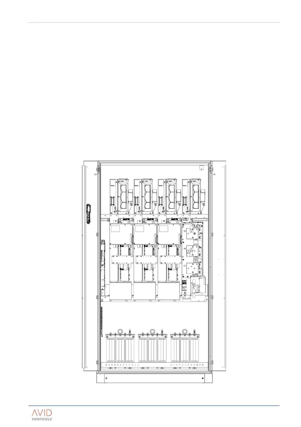
3.6.9 Typical CDM Arrangement
Figure 3–6. – Typical Layout Of CDM (DFE Drive)