T1689 Technical Manual Rev 07 Specification
MV3000 Air Cooled DELTA User I/O Termination Panel
Page 27
2.4.2 Weight
The MV3000e controller weighs approximately 4 kg (8.8 lb.).
2.4.3 Optional Modules
Several optional communication modules are available for retrofit to the standard MV3000e controller:
• MVC3007-4002 Profibus field coupler 12 Mb/s;
• MVS3011-4001 2
nd
CAN port communications module;
• MVS3012-4001 Ethernet interface, single channel;
• MVS3012-4002 Ethernet interface, dual channel.
Installation and operation instructions are supplied with each module, see Section 1 - Introduction.
2.5 USER I/O TERMINATION PANEL
Unit covered: MVC3002-4001
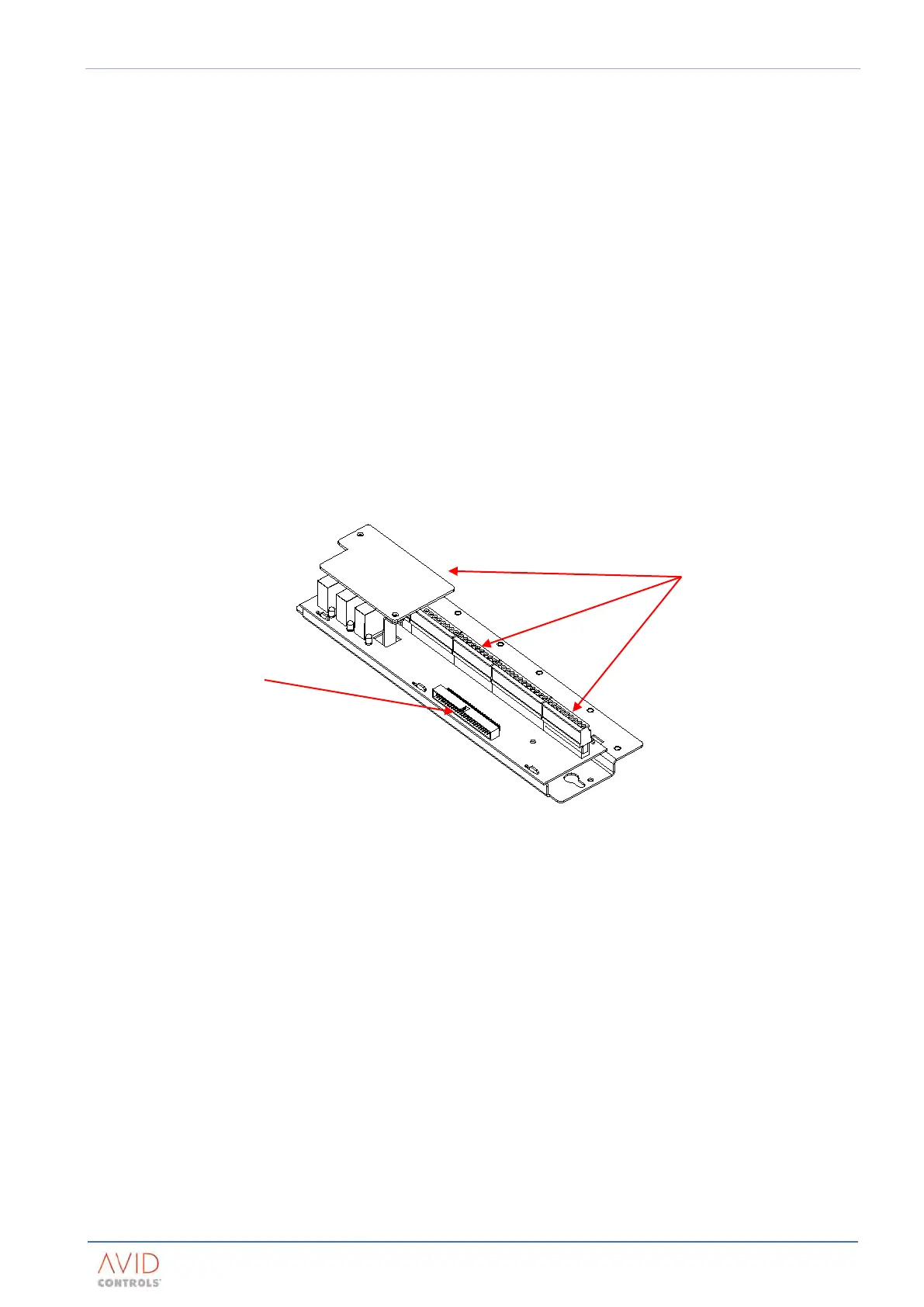
The user termination panel, shown in Figure 2–2, provides connection facilities for I/O signals to and from the
MV3000e drive.
Figure 2–2. – User I/O Termination Panel
Except for connections to TB1, TB2, and TB3, multicore-screened cables should always be used. For each
screened cable, crimp the braid to an M4 (No. 8 or 3/16 in) ring crimp and secure it to the panel with the M4
screws provided.
The user connectors on the user I/O termination panel are suitable for 0.5 mm
2
- 2.5mm
2
(20 to 14 AWG) single
core or flexible cable. A consolidating crimp should be used for the minimum size. Refer to table below for a
specification of each terminal function.
Refer to the Commissioning section of T1676 or T2002 MV3000 Getting Started Manuals for basic I/O
configuration.
Plant I/O is configured by Menu 7 of the MV3000 firmware. Refer to T1679 MV3000 Software Manual for
details of Menu 7.
There are two DIP switches on the module (see Figure 2–3) that configure the analogue I/O for current or
voltage operation. Further parameterisation is done through Menu 7 of the MV3000 firmware.
NOTE: TB4 and TB6 are each 9 way terminal blocks of the same connector pitch and so it is important that wiring for
these blocks is connected to the correct terminal block. TB1 is also a 9 way terminal block but this has a
different connector pitch to TB4 and TB6.
TB1 to TB6 user I/O terminals
PL1 – 50 way ribbon cable
connector to controller