T1689 Technical Manual Rev 07 CDM Commissioning Guidance
MV3000 Air Cooled DELTA Electrical Safety Tests
Page 131
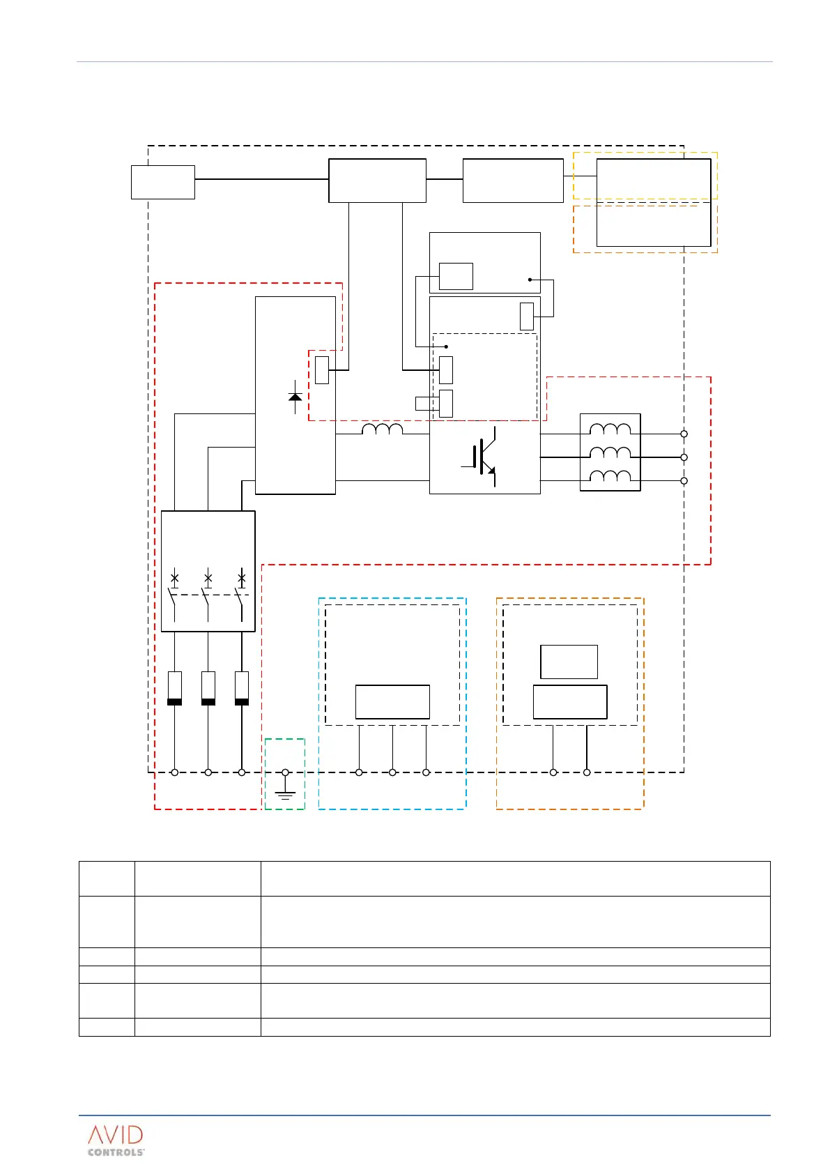
6.3.3 Voltage Groups For Insulation Tests
For the insulation tests, drive systems can be considered to consist of several different voltage groups, see the
typical system example in Figure 6–1 and Table 6–1.
R S T
U
V
W
SHARING
REACTOR
RECTIFIER
MVC3003-40xx
SMPS
DC+
DC-
U
V
W
PL1
TB1
PL2
PL2
Interlock
DIB
PL3
DC +/-
RECT +
RECT -
R
S
T
MAIN AC
CIRCUIT
BREAKER
415 Vac Auxiliary
Components
110 / 230 Vac Auxiliary
Components
Fans
Contactors
Contactors
MVC3001-400x
CONTROLLER
MVC3002-4001
I/O PANEL
KEYPAD
TB1
110 V ac / 230 V ac
PLANTSIDE I/O
<30 V ac / < 50 V dc
PLANTSIDE I/O
A
B C
C
E
D
DELTA
MODULE
Figure 6–1. – Voltage Grouping For Insulation Tests
Nominal Circuit
Operating Voltage
A
Or
The main power circuit – includes main fuses, main isolator, DELTA module power
connections, input, d.c. link and output reactors
Auxiliary circuits - may include coolant circuit pumps, fans and contactors
Auxiliary circuits - may include coolant circuit pumps, fans, contactors and plant I/O
Extra Low Voltage (ELV), such as plant I/O circuits
Main enclosure earth point, enclosure structure, other earthed metalwork etc.
Table 6–1. – Voltage Grouping For Insulation Tests