Introduction T1689 Technical Manual Rev 07
Drive Configurations MV3000 Air Cooled DELTA
Page 16
1.4 DRIVE CONFIGURATIONS
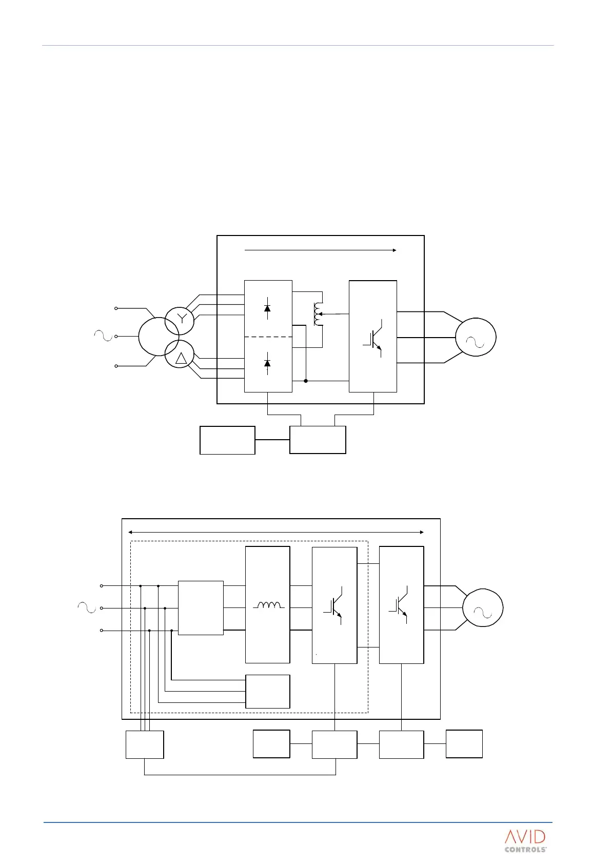
A DELTA drive consists of two ‘bridges’ – the network bridge and the machine bridge.
Two generic configurations are available, each with a different network topology:
• Diode Front End (DFE) – power transfer from the network to the load only;
• Active Energy Management (AEM) – power transfer to and from the network.
Both the DFE and AEM drives share the same machine bridge topology.
Figure 1–1 is a simplified schematic diagram of a DFE system. Figure 1–2 is a simplified schematic diagram of
an AEM system.
Circuit diagrams for the various drive configurations are included in:
Appendix B: Electrical Connection Diagrams.
Figure 1–1. – Schematic Diagram of a DFE DELTA System
POWER FLOW
Controller
User I/O
+
Machine
Bridge
-
+
-
Network
Bridge
AEM Dr ive
Line Reactor
PWM Filter
Controller
User I/O
Motor
SFE
MVM
Precharge
Circuit
Figure 1–2. – Schematic Diagram of an AEM DELTA System
POWER FLOW
MOTOR
Controller
User I/O
+
Machine Bridge
-
+
-
Interbridge
Transformer
Network Bridge