CDM Assembly T1689 Technical Manual Rev 07
Fitting Earth Bonding Plates MV3000 Air Cooled DELTA
Page 124
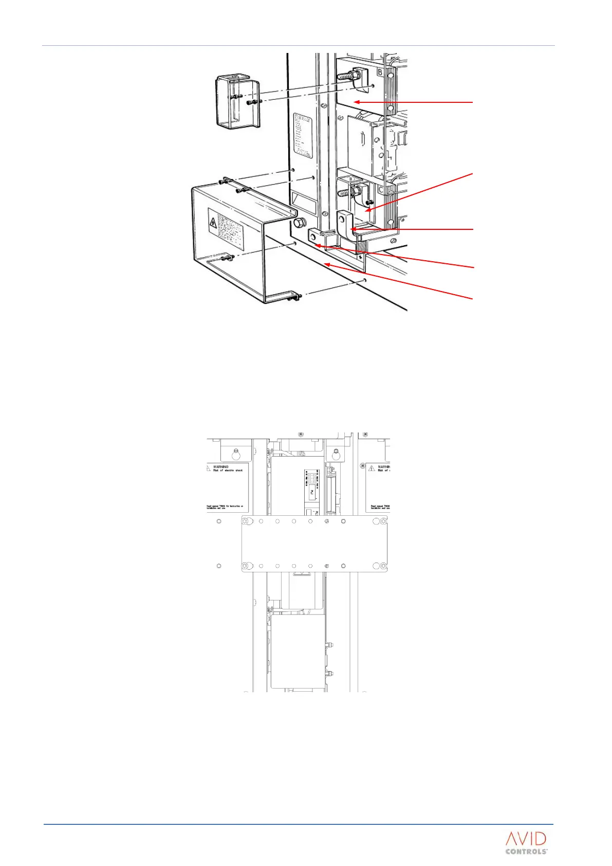
Figure 5–13. – MV DELTA Transistor Bridge Power Connections & Shrouding Details
5.14 FITTING EARTH BONDING PLATES
Each DELTA transistor module is supplied with a bonding plate. These plates must be fitted between adjacent
DELTA transistor modules as shown in Figure 5–14. The bonding plates are secured to the transistor module
chassis with four M5 x 10 SEM Torx screws which are supplied with the DELTA transistor modules.
Figure 5–14. – DELTA transistor bonding plate fitment
A similar bonding plate system should be incorporated to link the DELTA transistor modules to the controller
and enclosure frame. Since controller location may vary from installation to installation, this is the
responsibility of the drive designer.
Where multiple sections of plate are used, they must be in direct metal-to-metal contact with each other,
without intervening paint or wires.
B Phase stud type
connection
C Phase stud type
connection
DC+ insertion type
connection
DC+ insert type
connection
Earth insertion type
connection