Specification T1689 Technical Manual Rev 07
User I/O Termination Panel MV3000 Air Cooled DELTA
Page 28
2.5.1 Electrical Connections
The connections from the I/O panel to other equipment in the DELTA drive are as follows:
• One 50 way ribbon cable (925 mm [36.4 in] long), supplied with the I/O termination panel,
connects to the controller.
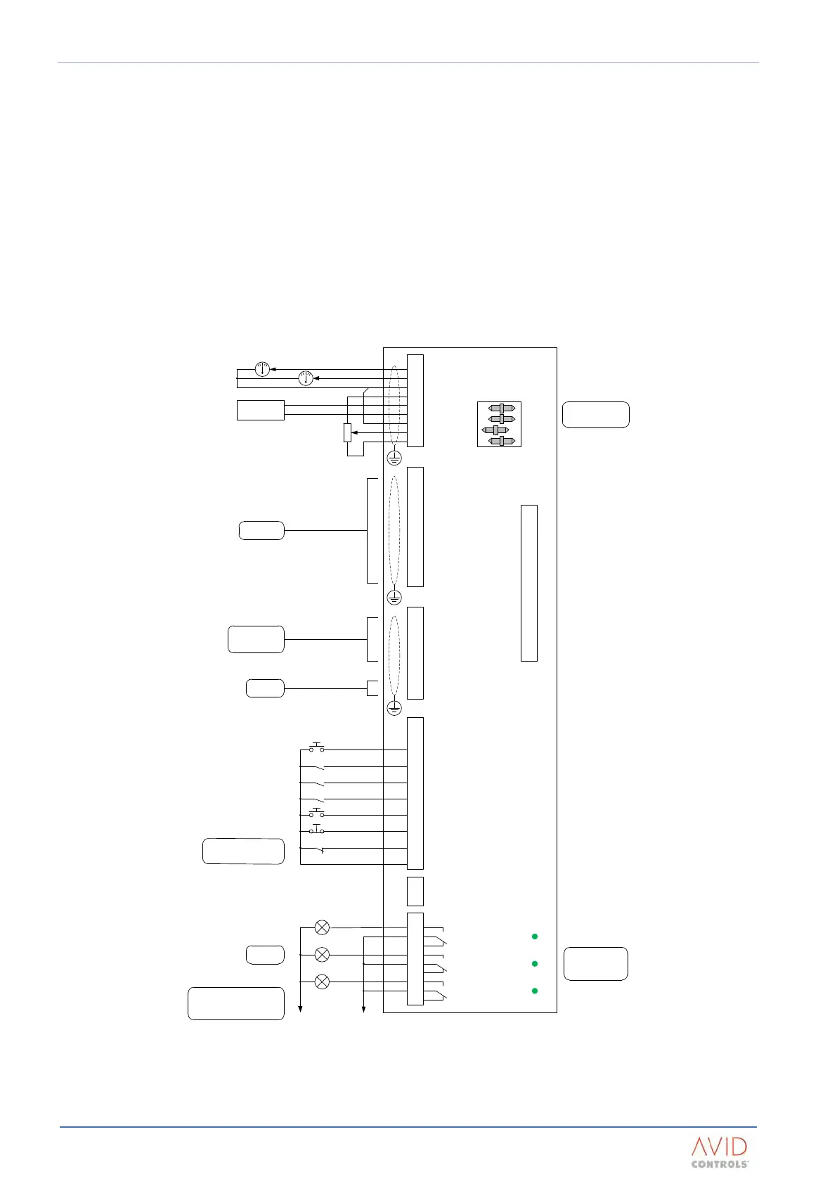
The user connections made available by the I/O panel are:
• TB1 - Digital outputs (three);
• TB2 - 24 V d.c. auxiliary input;
• TB3 - Digital inputs (six), interlock, 24 V peripheral supply;
• TB4 - Communications (RS485, HSIO);
• TB5 - Encoder / PTC (Thermistor, positive temperature coefficient);
• TB6 - Analogue I/O (2 inputs, 2 outputs).
Current Feedback
Speed Feedback
REF1 : +/ - 10V
11
TB5
1
2
3
5
4
6
7
9
8
10
12
TB4
1
2
3
5
4
6
7
9
8
10
TB3
1
2
3
5
4
6
7
9
8
TB1
1
2
3
5
4
6
7
9
8
1
2
3
5
4
6
7
9
8
TB6
20k
REF2 : 4 – 20mA
LOOP
From encoder
and motor PTC
To programmable
logic controller etc.
(optional)
AN O/P 2
AN O/P 1
AN GND
AN I/P 2-
-10 V
AN I/P 2+
AN I/P 1-
+10 V
AN I/P 1+
M_PTC
FB-
0 V
FB+
+5 V
+24 V
Z-
B-
Z+
B+
A+
A-
RS485 Tx+
RS485 Tx-
RS485 Rx+
GND
RS485 Rx-
HSIO-
HSIO+
+
+
-
-
TB2
1
2
0 V AUX INPUT
+24 V AUX INPUT
TRIP RESET
ANALOGUE REF 1/2
KEYPAD / REMOTE
REVERSE
RUN
STOP
PLANT INTERLOCK
+24 V O/P
0 V (digital)
High speed
digital I/O
(open = Ref 1)
(open = keypad)
NOTE:
To run the drive, INTERLOCK
must be connected to +24 V
DIG IN 6
DIG IN 5
DIG IN 4
DIG IN 2
DIG IN 3
DIG IN 1
INTERLOCK
+24 V O/P
DIG OUT 1
DIG OUT 2
DIG OUT 3
AT SPEED
OUTPUT
RUNNING
HEALTHY
0 V 24 V
NOTE:
0 V and 24 V supplies are available
at TB3 pins 1 and 2 but there is a
maximum load capability
D77
D76
D75
Lamps on
cubicle door
LED’s D75 to D77
indicate digital output
status. Illuminated is
equivalent to ON
DIP switch settings are
shown in their factory
default positions
AN O/P 2
AN O/P 1
AN I/P 2
AN I/P 1
1
2
4
C
20 mA 10 V
PL1
N/C
N/C
Figure 2–3. – Wiring Diagram For User I/O Termination Panel