T1689 Technical Manual Rev 07 Drive (CDM) Design
MV3000 Air Cooled DELTA Component Selection – Electrical
Page 97
3.8.5 Fuse Selection & Mounting
Fuses from other manufacturers may be used in place of those specified in Table 2–15 and Table 2–18, for use
with the Rectifier and Transistor Modules if they give equivalent performance.
• Semiconductor fuses usually require a minimum sized busbar connection and have limits on local
ambient temperature – refer to the manufacturer’s data.
3.8.5.1 Fuse Micro-Switch Attachment
For fuse indication a micro-switch attachment should be fitted to each fuse. The micro-switch should be
connected as shown in the circuit diagrams in Appendix B: Electrical Connection Diagrams.
3.8.6 Pre-Charge Requirements
MV3000e drive systems require a pre-charge routine to be in place to establish the d.c. link operating voltage
of the system.
3.8.6.1 Pre-charge for DFE systems
For DFE systems, the pre-charge circuitry is integrated into the MVR and GDR modules.
Upon the connection of the external a.c. supply, a controlled charging of the internal capacitor bank will be
carried out. Once the internal d.c. is established, the SMPS modules power up the controller. This will
interrogate the d.c. voltage and if the correct conditions are present, will initiate a “pre-charge complete”
signal and allow the drive system to become operational.
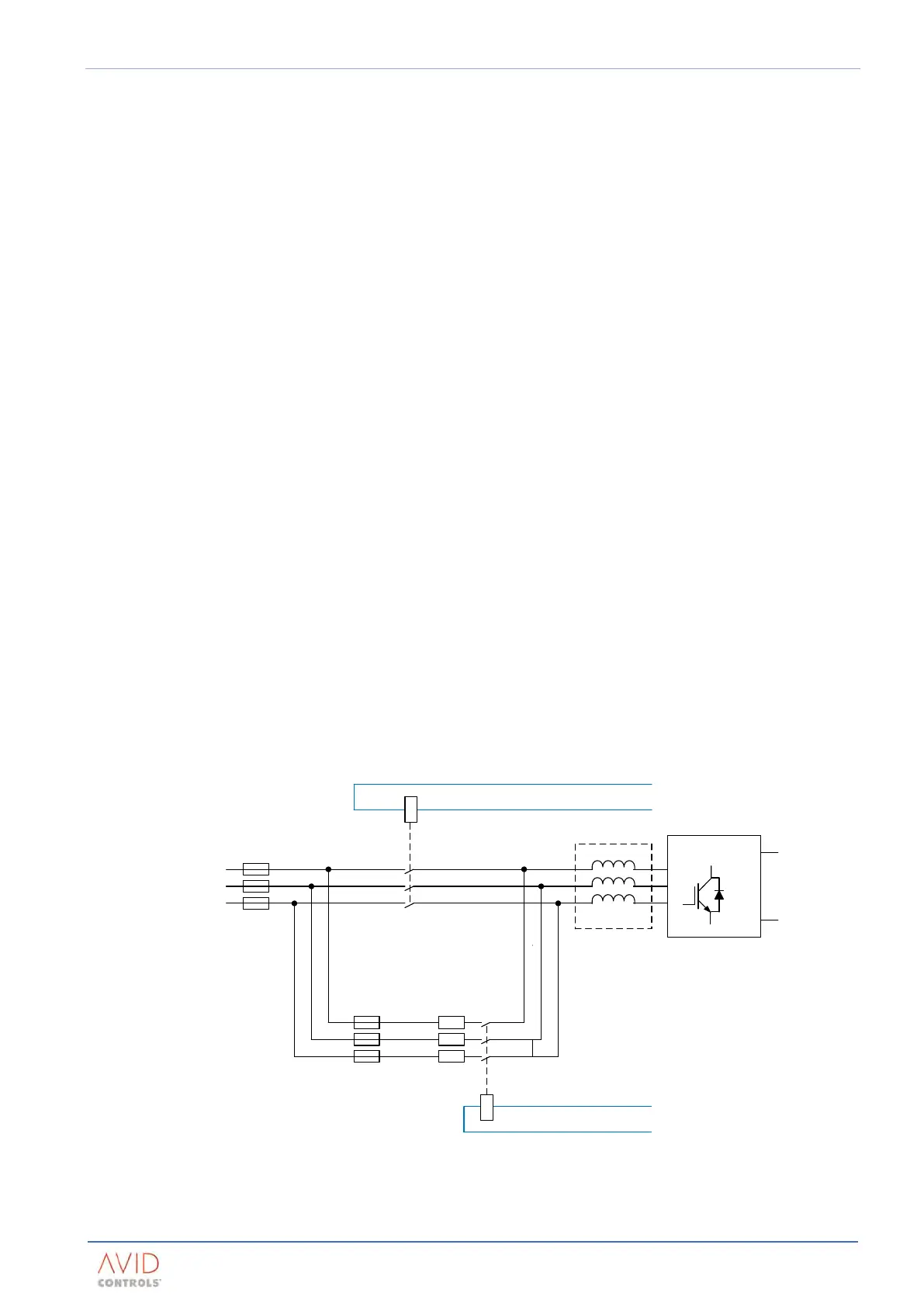
3.8.6.2 Pre-charge for AEM systems
For AEM systems, this is achieved by a pre-charge resistor and contactor in parallel with the main supply
(network) contactor. The pre-charge sequence is initiated manually or automatically and is controlled by the
MV3000e Common Drive Controller (CDC). Completion of the pre-charge event is indicated by the CDC, which
then allows full power operation to begin.
A Pre-Charge representation for an AEM system configuration is shown in Figure 3–8.
Network Bridge
Control
Control
Supply
Re
act or
Pre-Charge
Contactor
Pre-Charge
Resistors
Pre-Charge
Fuses
Main Supply
Contactor
Main a.c.
Supply
Figure 3–8. – AEM Pre-Charge Arrangement