CDM Assembly T1689 Technical Manual Rev 07
CONTROL CONNECTIONS - RIBBON CABLES MV3000 Air Cooled DELTA
Page 126
5.18 CONTROL CONNECTIONS - RIBBON CABLES
5.18.1 Fitting Screened Ribbon Cables
The ribbon cables used in the DELTA drive are screened to prevent the electrical noise generated by the drive
from interfering with control signals. It is therefore very important that these cables are fitted correctly.
The screen is exposed at each end of the ribbon cable, and this exposed area should be located in the two-
piece clamps provided with the products (or available separately), and the clamps tightened.
NOTE: The correct clamp should be chosen for securing the 40-way DELTA ribbon cables at the controller. Clamp
sets are available to secure from one to six ribbon cables.
Only ribbon cables supplied by GE Power Conversion must be used. This is to ensure that the screen is of a
suitable construction and performance, enabling the clamps described in Section 2.15.2 – Ribbon Cable
Clamps to correctly secure the ribbon cables.
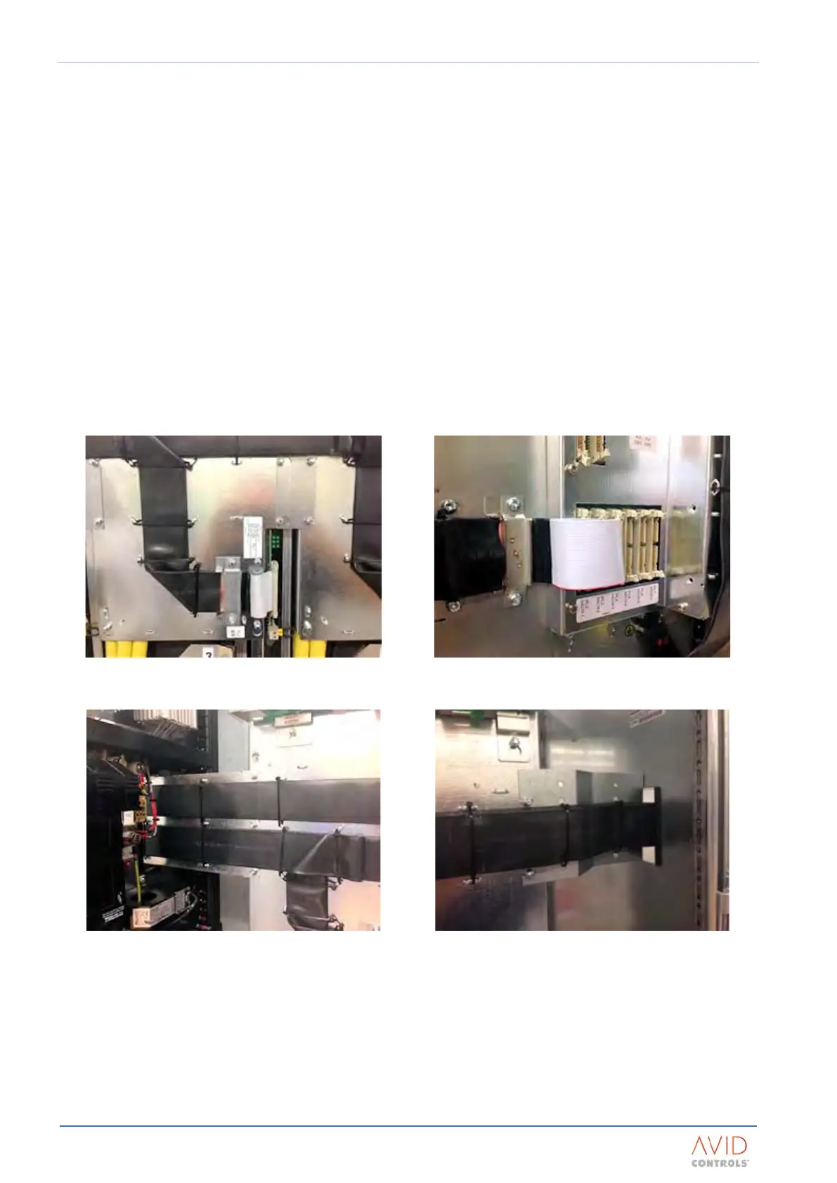
Ribbon cables should be routed flat to earthed steelwork where possible and secured at regular intervals with
cable ties or similar mechanical restraints. Typical ribbon cable installations are shown in Figure 5–16 to Figure
5–19.
NOTE: Ribbon cables must not be run in front of the ribbon header of another DELTA module.
Figure 5–16. – Ribbon Cable Clamp At The DELTA
Transistor Module
Figure 5–17. – Ribbon Cable Clamp At The DELTA
Controller
Figure 5–18. – Typical Ribbon Cable Routing Across The
DELTA Transistor Modules
Figure 5–19. – Typical Ribbon Cable Routing Between
Enclosures
5.18.2 DELTA Transistor Modules
DELTA transistor modules are connected to the controller with a 40 way screened ribbon cable. PL1 of DELTA 1
should always be connected to PL2 on the controller. PL1 on the remaining DELTA transistor modules should
be connected in ascending order as shown in Appendix B: Electrical Connection Diagrams.
 Loading...