R5905754 /13 DPxK-32B 31
CAUTION: The cross-sectional area of the conductors in the Power Supply Cord shall not be less
than 4 mm
2
or AWG 10.
Required tools
• Flat torque screw driver 4 mm
• Adjustable wrench
Required parts
• (for 3W+N+PE, 230/400V) Certified power cable, minimum 4 mm² or AWG 10, 500V rated, cable diameter
between 11 mm and 21 mm or
• (for 3W+PE, 208V) Certified power cable, minimum 4 mm² or AWG 10, 300V rated, cable diameter
between 11 mm and 21 mm
• Circuit breaker maximum 40A
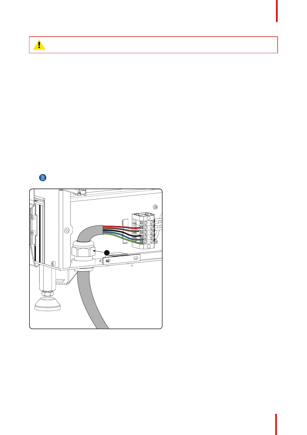
How to connect
1. Remove the back cover.
2. Remove the power input cover.
3. Loosen the cable gland fixation ring (1).
Note: The cable gland (1) is specified for cables with a diameter between 11mm and 21mm.
Image 3-12: Power cable connection
4. Push the stripped power supply cable through the cable gland. When using a flexible power cord, make sure
that each conductor end is provided with an end sleeve.
Fix the cable in the cable gland by securing ring 1 with an adjustable wrench.
5. Connect the power cord with the terminal barrier strip. Use a flat torque screw driver set to 1.4 Nm.
Always connect the ground wire (PE) with the connector indicated with PE on the terminal barrier strip.
If a neutral conductor is available, connect always to the connector indicated with N on the terminal barrier
strip
Physical installation
 Loading...