8. Light processor assembly
8.12 Replacement of the Light Sensor Module
Purpose of the Light Sensor in the Light Pipe
To obtain a Constant Light Output (CLO) from the projector a light s ensor is m ounted just behind the fold mirror. On a regular bas e
the controller of t he projector read the measured values of this light sensor and, if required, s ends corrective information to the Lamp
Power Supply (LPS).
The left cover h as to b e removed from the projector to replace the Light Sensor M odule. This pro cedure a s-
sumes that the left cover is already removed f rom the p rojector.
Necessary tools
• TX10 Torx screw driver.
• Light meter.
How to replace the Light Sensor Module of the Light Processor
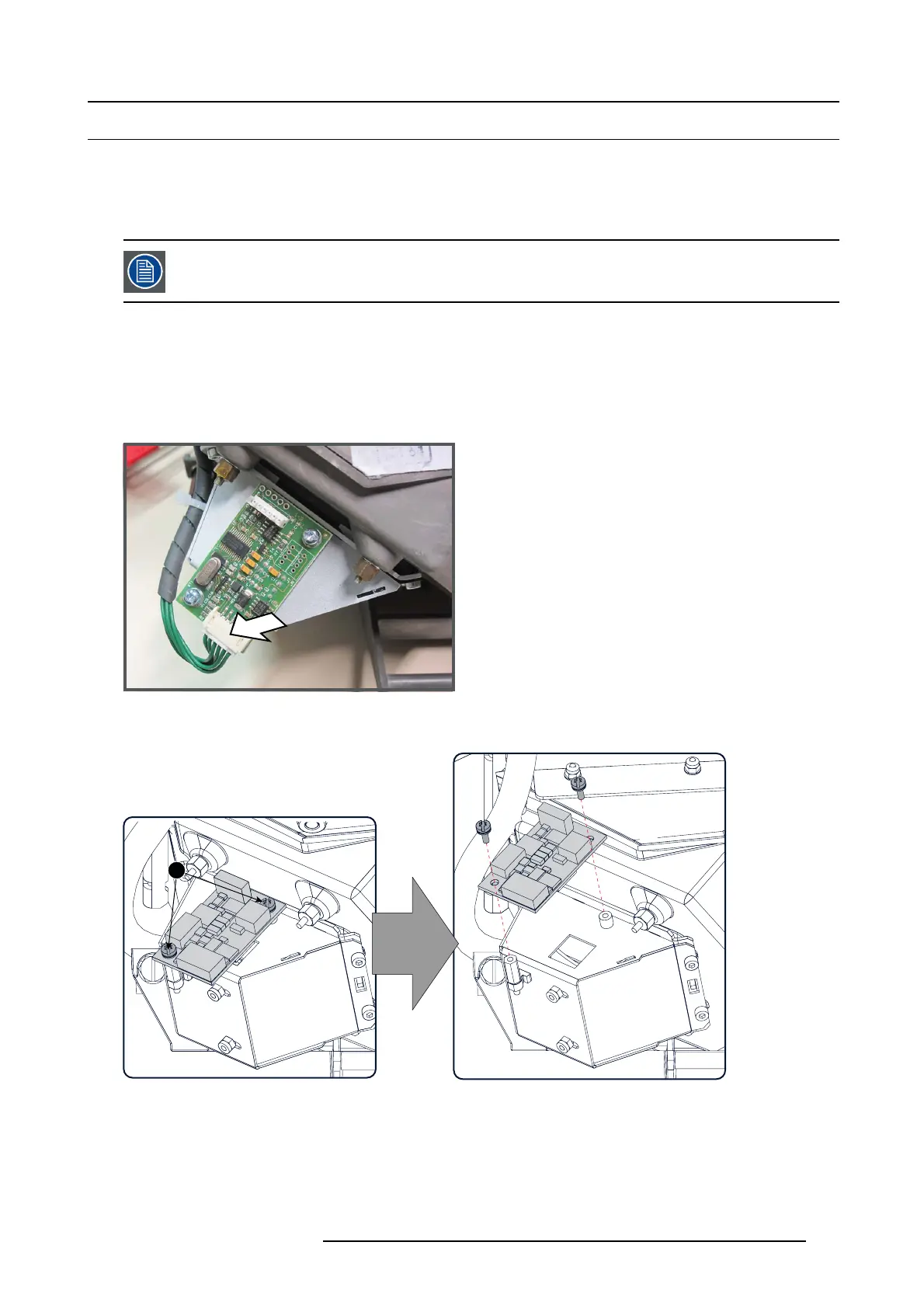
1. Disconnect the wire unit from the Light Sensor Module.
Image 8-17
Light sensor connection
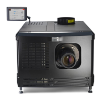
2. Remove the Light Sensor M odule by releasing the two Torx screws (reference 1). Use a TX10 Torx s crew driver.
1
Image 8-18
Light sensor unit removal
3. Install a new Light Sensor Mo dule. Use a T X10 Torx screw driver to fasten both screws (reference 1).
4. Reconnect the wire unit with Light Info M odule (image 8 -17).
5. Place a light meter in the center of the screen and c alibrate the Light Sensor Module. For detailed instructions see user guide of
the Communicator software.
R5905043 DP2K-12C/11CX 19/02/2018
151