11. Lenses and Lens holder
1
2
3
4
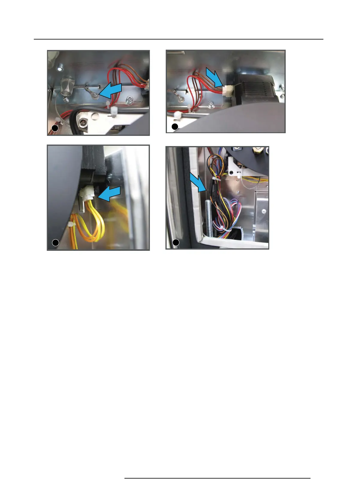
Image 11-16
Electrical connections, image view
2. Plug in the connector of the top motor (image indication 2) (brown and red wires).
3. Plug in the connector of the right motor (image indication 3) (yellow an d orange wires).
4. Connect all connectors of the wire set (4x 2 pins connectors and 2x 6 pins connectors) (image indication 4).
Connect those c onnectors with each o ther that hav e the same colored wires and exact the s ame position.
5. Bundle the cables together with a wire tie.
R5905043 DP2K-12C/11CX 19/02/2018
191

 Loading...


