17. Lamp power supply
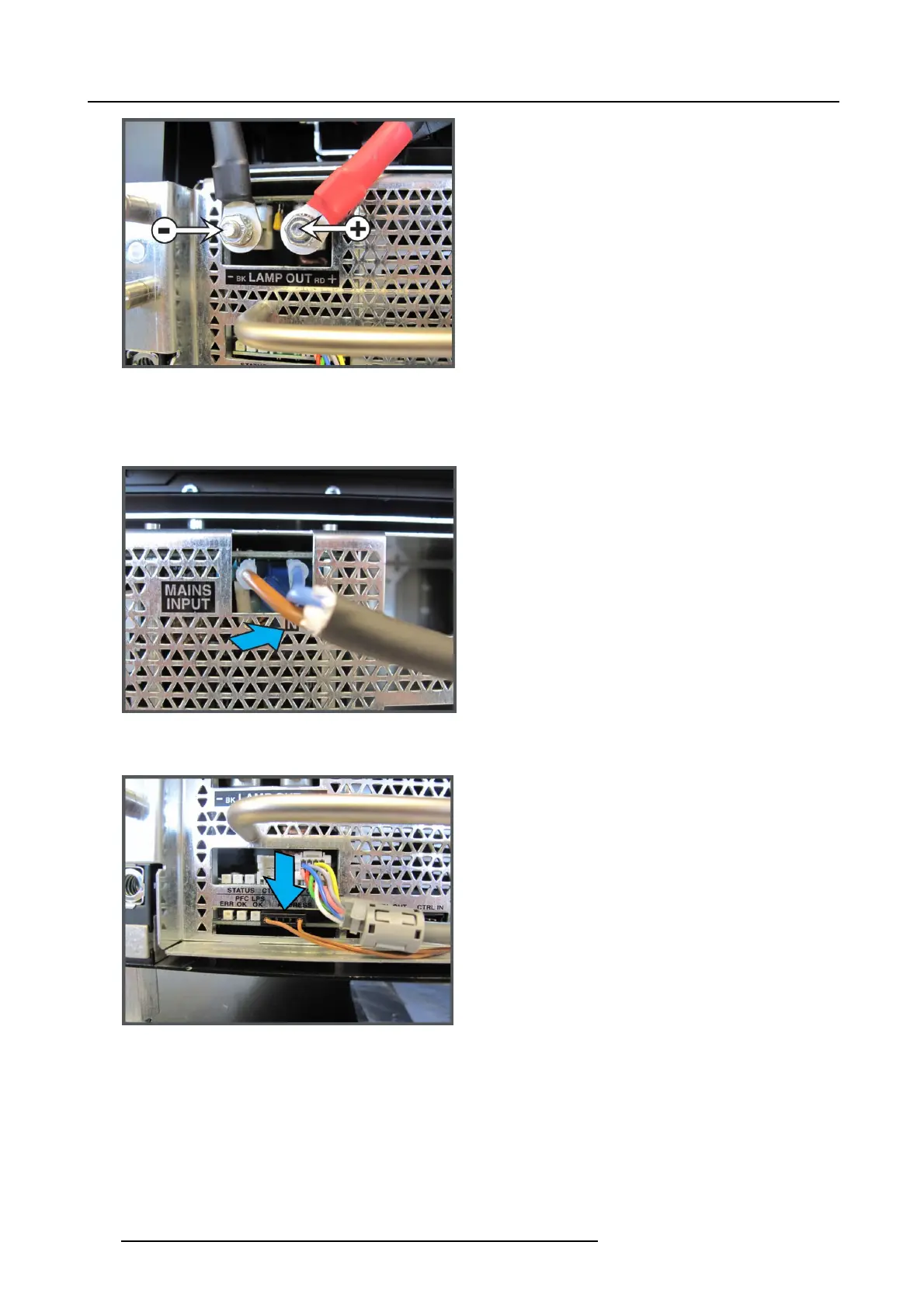
Image 17-12
Lamp power cables
4. Connect the c ontroller wire unit with the “CTRL IN” socket of the LP S unit a s illustrated.
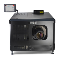
5. Connect the mains input cab les with the “MAINS INPUT” sockets of the LPS modu le as illustrated.
If a n eutral ’N’ indication is av ailable, plug the con nector of the blue wire into the socket labeled with N.
Image 17-13
Mains input connection and neutral indication (if available)
6. If not yet available, plug in the previously removed “ADDR ES S” wire unit.
Image 17-14
Address connection
290 R5905043 DP2K-12C/11CX 19/02/2018