ELECTRICAL SYSTEMS - CHASSIS — 9
176
20 08 CONTESSA
CHASSIS ELECTRICAL - INTRODUCTION
This section contains guidelines, procedures
and information that will assist in understanding
the chassis electrical system and the operation
of various components. Refer to the OEM
manuals included in the Owner’s Information
File box for their respective, in-depth, individual
component operating instructions.
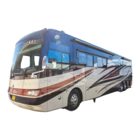
BATTERY DISCONNECT - CHASSIS
The main battery
disconnect switch located
in the rear curbside bay
controls the DC power to
the front electrical bay.
Most chassis and engine
functions are interrupted
when the battery
disconnect is turned
off. Some electronic
components of the engine and transmission
require a constant power source and will
continue to draw power when the disconnect is
engaged.
Turn the main battery disconnect switch off
when the motorhome is going to be stored or
when performing electrical maintenance. If
possible, leave the motorhome plugged into an
AC source with the battery disconnect switch on
to help prevent the possibility of dead batteries.
If an AC source is not available and the
motorhome is going to be stored more than 48
hours, it is recommended to turn the battery
disconnect switch off.
WARNING:
When welding is involved for
motorhome repair or modification,
only qualified, experienced technicians
should weld on the chassis. Improper
welding procedures and materials
may weaken the assembly or result in
damage that is not obvious and may not
cause an immediate problem or failure.
Unauthorized modifications or repairs
to the chassis could result in a forfeiture
of warranty coverage.
DANGER:
Due to the sensitive nature of the
electronics on the chassis, the following
precautions are required to protect
electrical components in the motorhome
chassis:
1. Disconnect the (+) positive and (-)
negative battery connection.
2. Cover electronic control components
and wiring to protect from hot
sparks.
3. Disconnect the terminal plugs from
the engine Electronic Control Unit,
located on the passenger side of the
engine block.
4. Disconnect all the plugs from the
transmission Electronic Control Unit,
located in the front electrical bay.
5. Disconnect the wiring from the
alternator.
6. DO NOT connect welding cables to
electronic control components.
7. Attach the welding ground cable no
more than two feet from the part to
be welded.
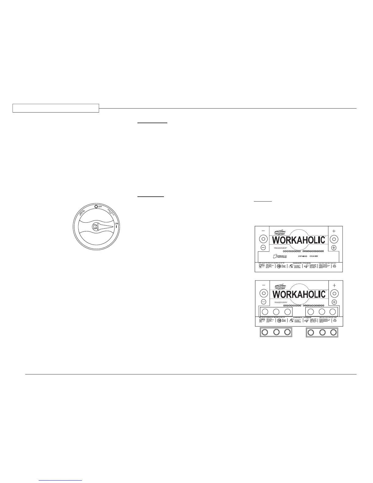
BATTERY - CHASSIS
The chassis battery is designed to produce high
amperage necessary to start the engine. Maintain
the chassis battery through regular electrolyte
level inspections and hydrometer readings.
High electrolyte consumption or inconsistent
hydrometer cell readings may indicate a
charging system problem. Perform a charging
system and current draw check if the battery is
exhibiting abnormal hydrometer readings.
NOTE:
Replacement batteries should have the
same cold cranking amp (CCA) rating.
080460
Battery with cover removed. Cut plastic to
remove cover.
Located in the rear
curbside compartment.
060350b