237
20 08 CONTESSA
CHASSIS INFORMATION — 10
Hydraulic Pump
The hydraulic pump creates pressure by
meshing sets of gears together inside a close
tolerance housing. A ltered supply of hydraulic
uid from the hydraulic reservoir enters the
intake side of the pump. The meshing gear
assembly “squeezes” the oil through the pump
to the output side delivering the pressurized
uid to the power steering gear and the
switching valve of the engine cooling system.
Each half of the pump is equipped with an
internal by-pass pressure relief spring. If the
hydraulic pressure should exceed the specied
pressure limit, the internal by-pass relief valve
will be forced open to keep the hydraulic uid at
operating pressure.
The hydraulic pressure generally is not rated
in psi but is rated in bars. One bar is equivalent
to approximately 14.5 psi. Hydraulic system
pressures with a system at no load may be as
low as eight bars on the output side of the pump.
This is due to the hydraulic uid ow of the
pump. When a load is placed on the hydraulic
pump, such as turning the steering wheel,
hydraulic uid ow slows from hydraulic uid
restriction and pressure increases. This may
be understood as a faucet with a garden hose
attached. Crimping the hose with the faucet
on will create pressure from the restriction.
This principle applies to the hydraulic system.
Consider the hydraulic pump as the supply
and the load as the power steering gear or the
hydraulic fan motors. Hydraulic system pressure
at full load can exceed 130 bar or 2000 psi.
Hydraulic system pressure falls dramatically
after the load. The return line pressure may be
as low as six to eight bars. The uid enters the
hydraulic cooler where the heat is dissipated.
Hydraulic Cooler
The hydraulic cooler prevents hydraulic uid
from overheating. When a load is placed on the
hydraulic system, heat is created in the uid.
Heat must be dissipated to prevent the hydraulic
uid from overheating and breaking down. After
cooling, the uid is ltered before returning to
the reservoir.
Care must be used when starting an engine
in very cold climates. As with any oil, lower
temperatures thicken the oil. Hydraulic system
pressure increases due to the viscosity of the
uid. Although the hydraulic pump is equipped
with pressure relief valves, the thick oil on the
return line can exceed the operating pressure of
the hydraulic cooler.
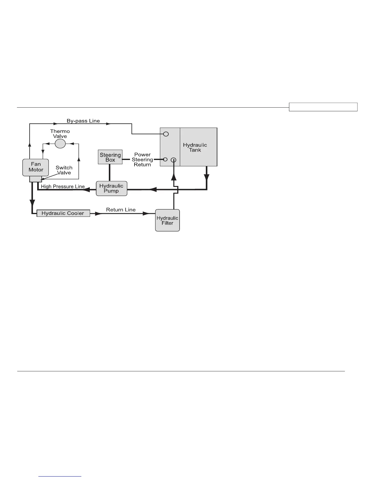
Hydraulic Fan System
The hydraulic fan drive system cools the
radiator, charge air cooler, hydraulic uid
cooler, transmission cooler and the dash air
conditioning condenser. The components
of the hydraulic fan system are: hydraulic
reservoir, lter, pump, hydraulic fan motor,
hydraulic switching valve and thermovalve.
Cooling fan speed is proportional to engine
speed and coolant temperature. When coolant
temperature rises above 185º F., the fan drive
controller slowly closes off the bypassing
100188c
Typical Hydraulic System Layout