Installing to NEMA-4 Specifications QTERM-G75 Terminal
26
Qlarity-Based Terminal Hardware
• Cut a hole in the panel and drill the mounting holes. See section 2.4.1, “Cutting Out the
Panel” for specifications.
• Install the QTERM-G75 terminal in the panel. See section 2.4.2, “Installing the Terminal”
for instructions.
• Connect cables to the terminal. Verify that the thumb screws are tight or the locks snapped
into place for each cable used.
• Apply DC power to the QTERM-G75 terminal. See section 2.4.3, “Applying Power” for
information.
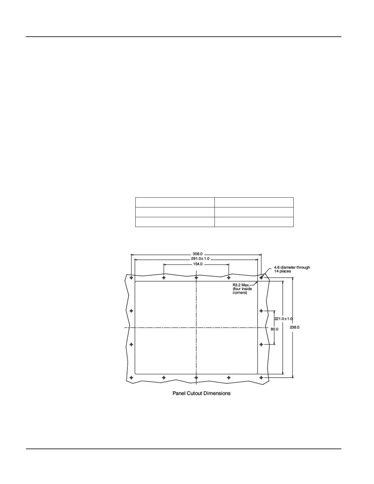
2.4.1 Cutting Out the Panel
The QTERM-G75 terminal can be mounted in panels from 0 to 12 mm thick. Fourteen screw
holes need to be drilled to install the terminal in the panel. The mounting holes should be 4.6
mm in diameter and drilled as shown in the figure below. Make a rectangular hole in the panel
using the following dimensions.
Figure 13 is a diagram of the landscape cutout.
File any rough edges smooth, especially on the face of the panel.
Landscape Portrait
Horizontal: 291 ± 1 mm Horizontal: 221 ± 1 mm
Vertical: 221 ± 1 mm Vertical: 291 ± 1 mm
Figure 13
QTERM-G75 Landscape Cutout