Installing to NEMA-4 Specifications QTERM-G75 Terminal
28
Qlarity-Based Terminal Hardware
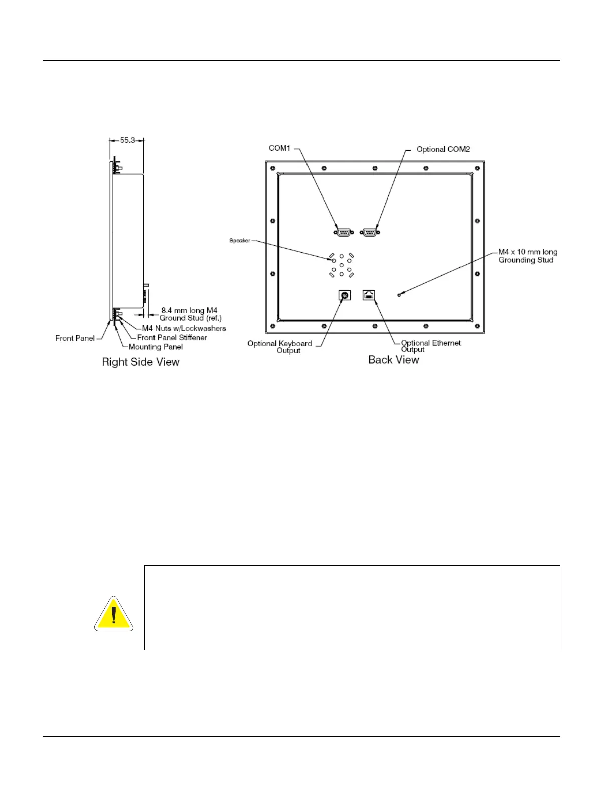
3. On the back of the panel, align the terminal mounting bracket holes with the mounting
studs and place the bracket against the back of the panel. Refer to Figure 15.
4. Attachments with lockwashers (supplied with the terminal) onto each of the fourteen
mounting studs. Tighten all nuts to create the seal between the terminal gasket and the
panel. Avoid overtightening the nuts.
2.4.3 Applying Power
Power is supplied to the QTERM-G75 terminal via the primary serial port connector. Refer to
section 2.2.1, “Serial Ports” for the pin assignments for power and ground. DC power must be
in the range of 8 to 26 volts (the current will vary depending on the input voltage; see table
below).
Figure 15
QTERM-G75 Back Panel Mount
CAUTION
QTERM-G75 power must come from an SELV (Safety Extra Low Voltage) power source
and should have a current limit on its output of 5 Amperes. It must provide a minimum of 8
volts DC power and be limited to a maximum of 26 volts DC. Limiting may be inherent to
the supply or may be provided by supplementary overcurrent devices. If the QTERM-G75
does not respond or exhibits abnormal behavior on power up, disconnect power and contact
Beijer Electronics for technical support.