QTERM-G58 Terminal Supported Interfaces
Qlarity-Based Terminal Hardware 67
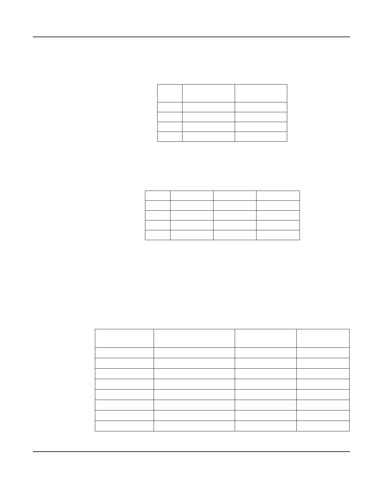
5.2.1.1 Power and USB Device Interfaces
The following table shows the pinout for the power and USB device interfaces.
5.2.1.2 Serial Multiprotocol Port Interface
The following table shows the connector pinout for the selected type of serial interface on the
mulitport.
5.2.1.3 Accessory Cable Wire Color Code and Demo Cable Pinout
The following table shows the wire color code for the 12-pin round connector to unterminated
(“blank”) accessory cable and the pinout to the demo cable, which terminates in a 15-pin
female D subminiature connector (DB15f). The cable contains fifteen conductors; however,
only twelve conductors are connected to pins on the round connector and DB15f. Ten of the
fifteen conductors in the cable are wired as 100 ohm twisted pairs, as shown in the table. One
of the fifteen conductors is a non-insulated drain wire that is shorted to the foil shielding in the
cable. This drain wire is not connected to the round connector or DB15f connector.
Pin
Regulated
(standard)
PC USB
Host Port
1 8 - 32 VDC 4.5 - 5.5 VDC
2 Ground Ground
11 N/A USB D+
12 N/A USB D-
Pin EIA-232 EIA-422 EIA-485
3 Tx Tx- RTx-
4 RTS (out) Tx+ RTx+
5 Rx Rx+ No signal
6 CTS (in) Rx- No signal
Round
Connector Pin
Wire Color Twisted Pairs
Demo Cable
DB15f Pin
1Brown –9
2 Red with Black Stripe – 1
3 Black Pair #1 4
4 White Pair #1 5
5 Red Pair #2 10
6 Green Pair #2 11
7 White with Red Stripe Pair #3 7
8 White with Green Stripe Pair #3 14