1 695 600 968 2019-01-28| Beissbarth GmbH
82 | MT ZERO 6 LCD | Initial commissioning
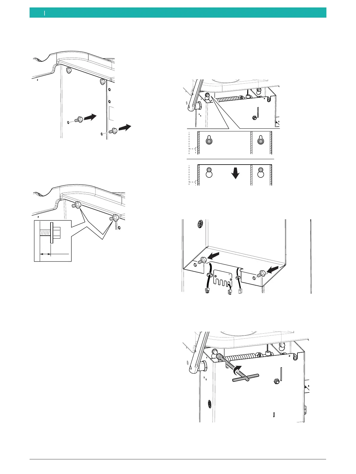
3. Remove the screws from the bottom holes on the
back of the casing.
651127-42_BM
Fig. 14: Removing the bottom screws
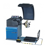
4. Position the screws and washers on the top
holes leaving at least 5mm of space between the
structure's wall and the washer.
≥5mm
651127-13_BM
Fig. 15: Positioning the top screws
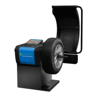
5. Anchor the protective hood of the moving unit by
aligning the top holes of the unit with the screws
previously put in place.
! Make sure not to crush the cables extending from
the bottom of the unit.
6. Push the unit down, and make sure the screws are
positioned correctly and as far in the holes as they
will go.
i The unit must be parallel to the structure.
651127-14_BM
Fig. 16: Anchoring the moving unit
7. Position the screws and washers previously removed
on the bottom holes, but do not tighten them yet.
651127-15_BM
Fig. 17: Positioning the bottom screws
8. Tighten the top screws on the holes in the unit with
the tool.
651127-16_BM
Fig. 18: Tightening the top screws
en