1 695 600 968 2019-01-28| Beissbarth GmbH
Maintenance | MT ZERO 6 LCD | 123
12.6.6 External laser indicator calibration
i The calibration plate is required for the calibration.
i The laser will only switch on if the wheel comes to a
stop at the position for attaching the clip-on balance
weight.
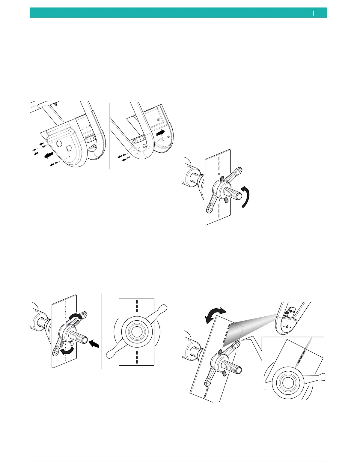
¶ Remove the cover of the sonar probe.
651127-85_BM
Fig. 106: Removing the cover of the sonar probe
The following describes 2 different procedures: one
for the mechanical version and one for the pneumatic
version.
Mechanical version
1. Remove any dirt on the flange with a wire brush.
2. Place the calibration plate included in the scope of
delivery against the flange's surface.
3. Lock the calibration plate by using a quick-clamping
ring and by inserting a small cone.
! Make sure the calibration plate is centered relative
to the flange shaft.
12
6
651127-88_BM
Fig. 107: Attaching the calibration plate
4. Close the wheel guard.
The measurement will start. Wait until the pro-
cess is completed.
After the start, the laser beam will be activated.
i Some machine versions require the wheel to be
positioned manually according to the instructions
shown on the monitor.
i During the calibration of the device, the laser beam
will be directed at the holes in the calibration plate.
5. Lift the wheel guard fully.
6. Release the quick-clamping ring to be able to turn
the calibration plate.
651127-89_BM
Fig. 108: Releasing the clamping ring
i Once the shaft rotates, the laser will be deactivated.
If necessary, reposition the shaft by hand.
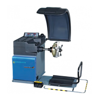
7. Turn the calibration plate, and hold it in place when
it is centered across from the shaft until the beam
intersects with the holes.
651127-90_BM
Fig. 109: Laser beam being emitted
en