1 695 600 968 2019-01-28| Beissbarth GmbH
102 | MT ZERO 6 LCD | Operation
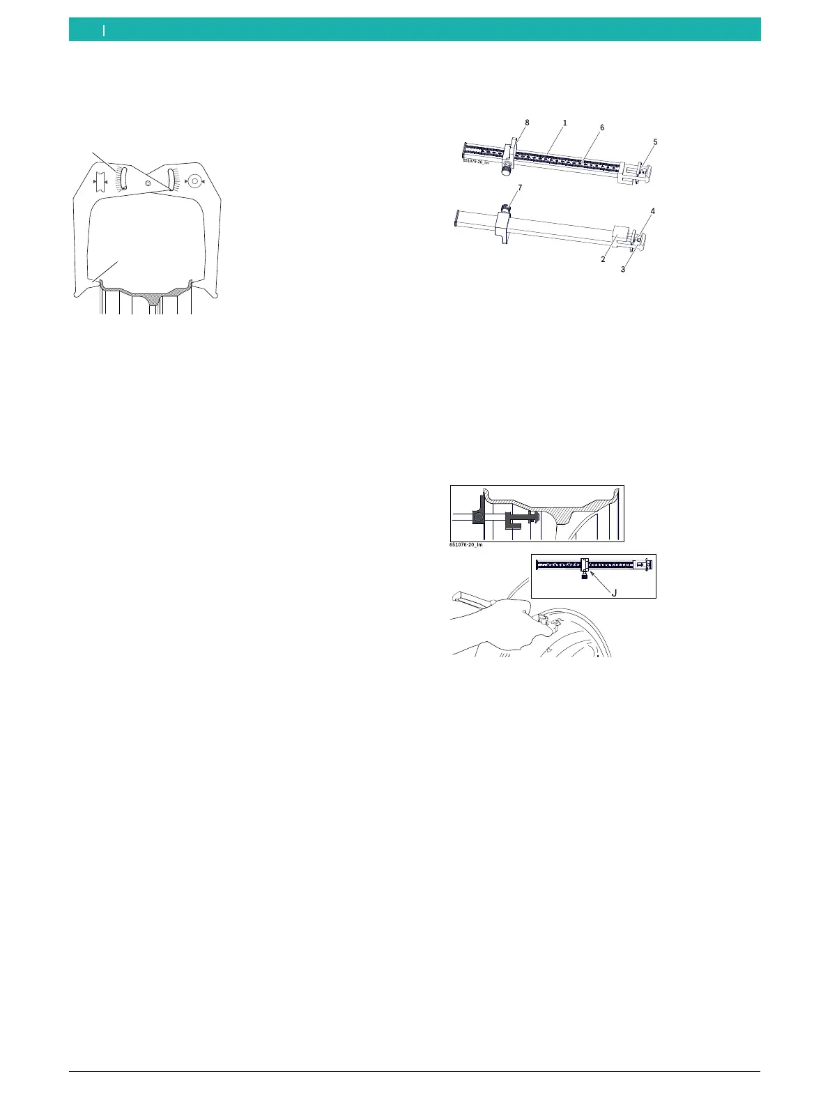
Rim width
1. Position the measuring compass as shown in the
figure.
2
1
Fig. 77: Determining rim data with the measuring compass
1 Rim width scale
2 Inner tip for rim width
2. Read off the rim width.
3. Press the <RIM WIDTH> key to change the value.
4. Use the <+> or <-> key to enter the recorded value.
" All the necessary rim data have been recorded.
8.9.2 ALU2 (PAX2), ALU3
Distance and rim diameter
Identical to the manual measurement for the Standard,
ALU1, ALU4, ALU5 and PAX1 balancing programs as well
as all static balancing programs.
Rim width (distance between the two balancing
planes)
i The manual rim-distance gauge can be used to
determine the rim width (distance between the
two balancing planes) in the Alu2, Alu3 and Pax2
balancing programs and to easily position and attach
the adhesive balance weights.
1. Select balancing program.
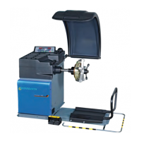
2. Position the slide with stop of the weight positioning
gauge (8) on the bead of the rim.
Fig. 78: Weight positioning gauge
1 Weight positioning gauge handle
2 Weight positioning gauge head
3 Inside balance weight holder
4 Ejector
5 Outside balance weight holder
6 Millimeter scale
7 Knurled screw
8 Weight positioning gauge slide with stop
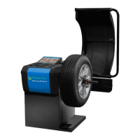
3. Place the outside balance weight holder (5) on the
plane where the balance weights are to be attached.
Fig. 79: Determining the measurement for an adhesive balance
weight
4. Tighten the knurled screw (7) to lock the determined
position.
5. Read off the value "J" on the millimeter scale.
6. Press the <RIM WIDTH> key to change the value.
7. Use the <+> or <-> key to enter the recorded value.
" All the necessary rim data have been recorded.
en