1 695 600 968 2019-01-28| Beissbarth GmbH
Initial commissioning | MT ZERO 6 LCD | 83
9. Tighten the bottom screws.
! Make sure the unit is parallel to the structure.
" This concludes the installation of the moving unit of
the protective hood.
4.5 Installing the support frame with
sonar
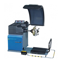
1. Remove the support frame taking care not to
damage the cables extending from it.
i The number of cables extending from the frame
varies depending on the machine's version. On the
wheel balancing machine with sonar functions and
laser, 2 cables are routed from the frame, while
there is just one cable on the version with sonar
only.
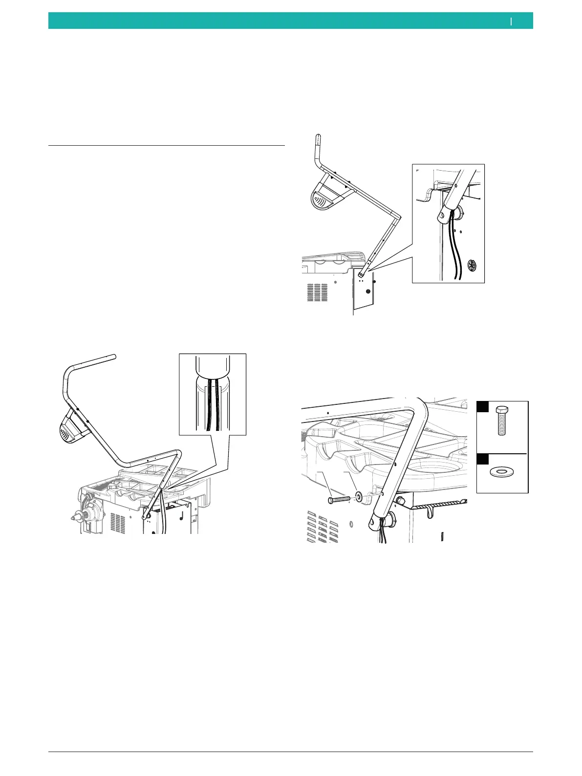
2. Position the support frame on the machine shaft
extending from the wheel guard moving unit.
3. Position the extending cables inside the receptacle
of the machine shaft extending from the unit.
651127-17_BM
Fig. 19: Preparation for installation
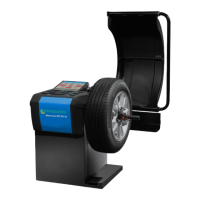
4. Connect the frame to the machine shaft. Proceed
with caution.
! Make sure not to crush the cables between the
machine shaft and the frame.
651127-18_BM
Fig. 20: Installing the support frame
5. Attach the screw set included in the scope of
delivery to the bottom hole.
i See the figure for the direction of installation.
651127-20_BM
1
2
M8x50
Ø8
n°1
1
n°1
2
Fig. 21: Fitting the bottom screw
en