1 695 600 968 2019-01-28| Beissbarth GmbH
Initial commissioning | MT ZERO 6 LCD | 81
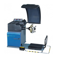
3. The wheel balancing machine must be secured to
the ground at a minimum of 3 places with screws
and dowels.
1
2
M8x70
8,5x24x4
n°3
n°3
3
Ø8
n°3
651127-11_BM
1
2
3
1
2
3
Fig. 12: Securing the MT ZERO 6 LCD
4. Insert the dowels provided, insert the washers
in between, and fully tighten them with a torque
wrench at a tightening torque of 25Nm.
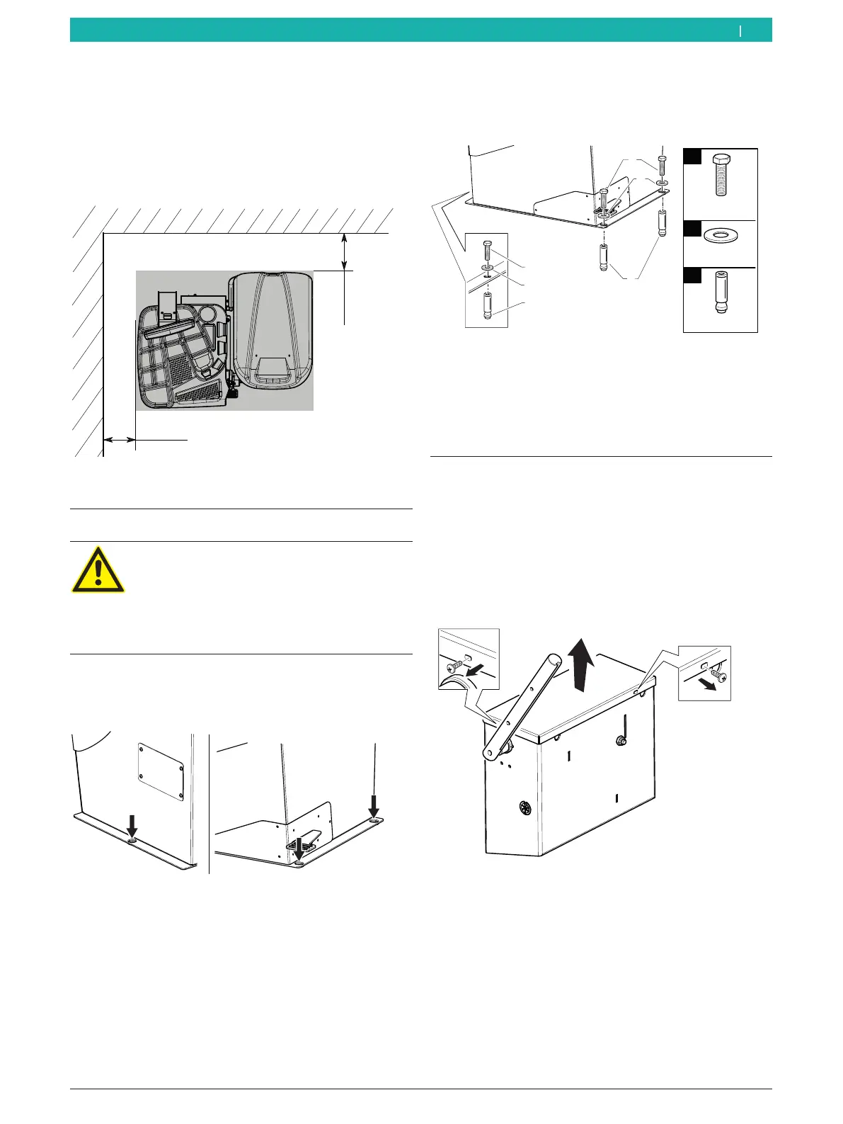
5. Set up the machine in the intended area, paying
attention to the specified safe distances.
i For safe and ergonomic operation of the wheel
balancing machine, it is advisable to set it up at a
distance of 500mm from the nearest wall.
500 mm
500 mm
651115-08_BM
Fig. 10: Safe distances
4.3 Floor mounting
Warning – danger of tipping!
Considerable forces are involved in the wheel
balancing process.
¶ Before using the machine, it is essential
to fasten it to the ground according to the
manufacturer's specifications.
1. Place the MT ZERO 6 LCD on the ground at the
intended final location. Use the bore holes in the
base of the machine for orientation.
651127-10_BM
Fig. 11: Overview of mounting holes
2. Position a power drill with a 14-mm bit, and drill
holes 65mm deep.
! We recommend cleaning the hole carefully before
inserting the dowel.
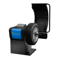
4.4 Installing the wheel guard moving
unit
i The screws for securing the unit are already
attached to the MT ZERO 6 LCD.
1. Remove the screws for securing the cover of the
unit's casing.
2. Remove the cover.
651127-12_BM
Fig. 13: Removing the cover
en