1 695 600 968 2019-01-28| Beissbarth GmbH
Initial commissioning | MT ZERO 6 LCD | 87
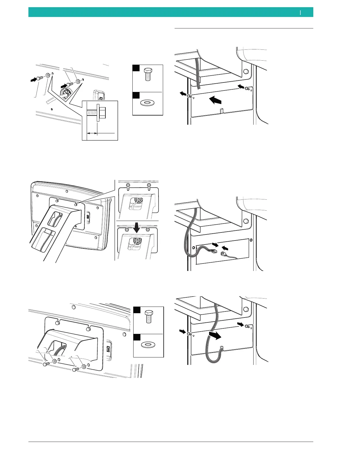
5. Position the screws and washers for fastening the
digital control panel in the holes provided for this
purpose at the top of the control panel, leaving at
least 5mm clearance between the wall and washer.
651127-30_BM
≥5mm
1
2
M5x12
Ø5
n°2
n°2
1
1
2
2
Fig. 37: Preinstalling the screws in the digital control panel
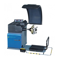
6. Fasten the digital control panel to the holder. Do not
crush the cable.
651127-31_BM
Fig. 38: Positioning the digital control panel
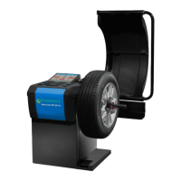
7. Position the screws and washers for fastening the
digital control panel in the holes provided for this
purpose at the bottom of the control panel.
651127-32_BM
1
2
n°2
n°2
1
2
1
2
M5x12
Ø5
Fig. 39: Fastening the digital control panel
8. Tighten the screws.
" Mounting the digital control panel is completed.
4.9 Digital control panel connections
1. Remove the connector plate.
651127-33_BM
Fig. 40: Removing the connector plate
i The cable for connecting the digital control panel is
lying loose in the connection area.
2. Remove the cable from the connection area.
3. Connect the cable from the digital control panel to
the cable in the connection area.
651127-34_BM
Fig. 41: Connecting the digital control panel
4. Mount the connector plate.
651127-36_BM
Fig. 42: Mounting the connector plate
" Connecting the digital control panel is completed.
en