1 695 600 968 2019-01-28| Beissbarth GmbH
84 | MT ZERO 6 LCD | Initial commissioning
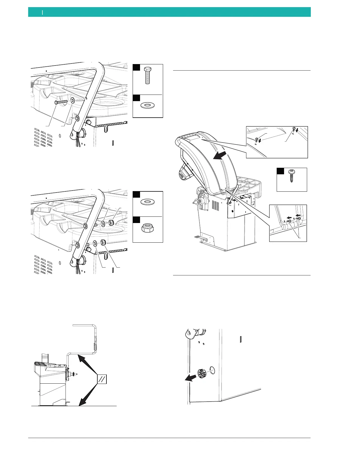
6. Screw the screw set included in the scope of
delivery into the threaded bore hole at the top.
i See the figure for the direction of installation.
651127-19_BM
1
2
M8x50
Ø8
n°1
1
n°1
2
Fig. 22: Fitting the top screw
7. Fit the screw set included in the scope of delivery
for attaching the frame on the machine shaft, but do
not tighten it yet.
651127-21_BM
1
2
M8
Ø8
n°2
1
1
n°2
2
2
Fig. 23: Fitting the fastening screws
! Perform a visual inspection to make sure the
support frame is parallel to the floor of the
structure.
Fig. 24: Ensuring the parallel alignment of the support frame
i The coupling for attaching the frame has some play.
If necessary, use it to set the correct position.
8. Tighten the screw set.
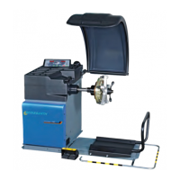
4.6 Installing the wheel guard
1. Remove the wheel guard.
2. Position the wheel guard on the frame in such a way
that the holes in the protective hood are aligned
with the holes in the frame.
3. Use the screw set included in the scope of delivery
to secure the wheel guard.
651127-22_BM
1
4,2x16
1
n°4
1
1
Fig. 25: Installing the wheel guard
4.7 Preparing the electrical connectors
i During this phase, the machine must not yet be
connected to the voltage supply.
1. Remove the grommet from the wheel guard moving
unit.
651127-23_BM
Fig. 26: Position of the grommet
en