1 695 600 968 2019-01-28| Beissbarth GmbH
Initial commissioning | MT ZERO 6 LCD | 85
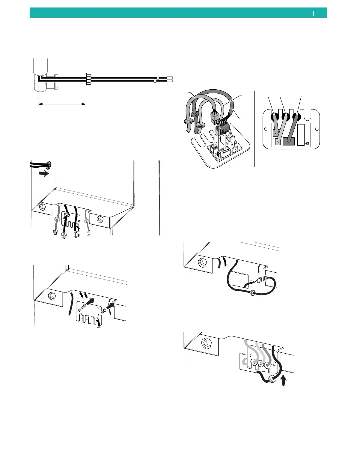
2. Place the cables extending from the support frame
into the receptacle of the grommet, and position the
grommet as specified by the dimensions listed here.
651127-24_BM
200 mm
Fig. 27: Dimensions for positioning the grommet
3. Position the cables in the receptacle of the
grommet, and guide them towards the bottom until
they extend from the casing of the unit.
4. Position the grommet in its receptacle again.
651127-25_BM
Fig. 28: Routing the cable through the unit
5. Uninstall the plate of the interface card.
Fig. 29: Uninstalling the plate of the interface card
6. Connect the connectors shown in this figure, and
position the cables in the notches on the interface
card plate.
i Insert the washers for routing the cables into the
notches of the plate.
651127-37_BM
1 2 3
3
2
Fig. 30: Interface card connections
1 Micro-switch cable
2 Magnetic-sensor cable
3 Sonar cable
i If present, connect the laser cable to the extension
inside the machine.
7. Connect the laser cable.
651127-63_BM
Fig. 31: Connecting an external laser cable
8. Position the washer for routing the cable in the
notch of the plate.
651127-64_BM
Fig. 32: Positioning the laser cable
en