1 695 600 968 2019-01-28| Beissbarth GmbH
92 | MT ZERO 6 LCD | Attaching and removing a wheel
6. Attaching and removing a
wheel
WARNING – wheel may slip!
Risk of crushing of fingers and other body
parts when attaching and removing the
wheel.
¶ Wear protective gloves.
¶ Wear safety shoes.
¶ Do not reach between the wheel and shaft.
¶ Always use two people to attach heavy
wheels.
6.1 MT ZERO 6 LCD AWx
6.1.1 Attaching a wheel
1. Switch on the MT ZERO 6 LCD AWx using the on/
off switch.
Wait for the software to load completely.
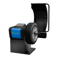
2. Position the correct cone on the shaft (flange).
Fig. 54: Positioning the correct cone on the shaft (flange)
3. Remove any dirt with a wire brush.
4. Rest the wheel on the shaft at the cone.
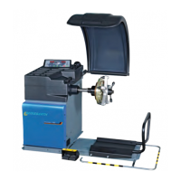
5. Slide the disengaged quick-locking ring onto the
shaft, and press it firmly against the wheel.
651127-71_BM
Fig. 55: Positioning the disengaged quick-locking nut on the shaft
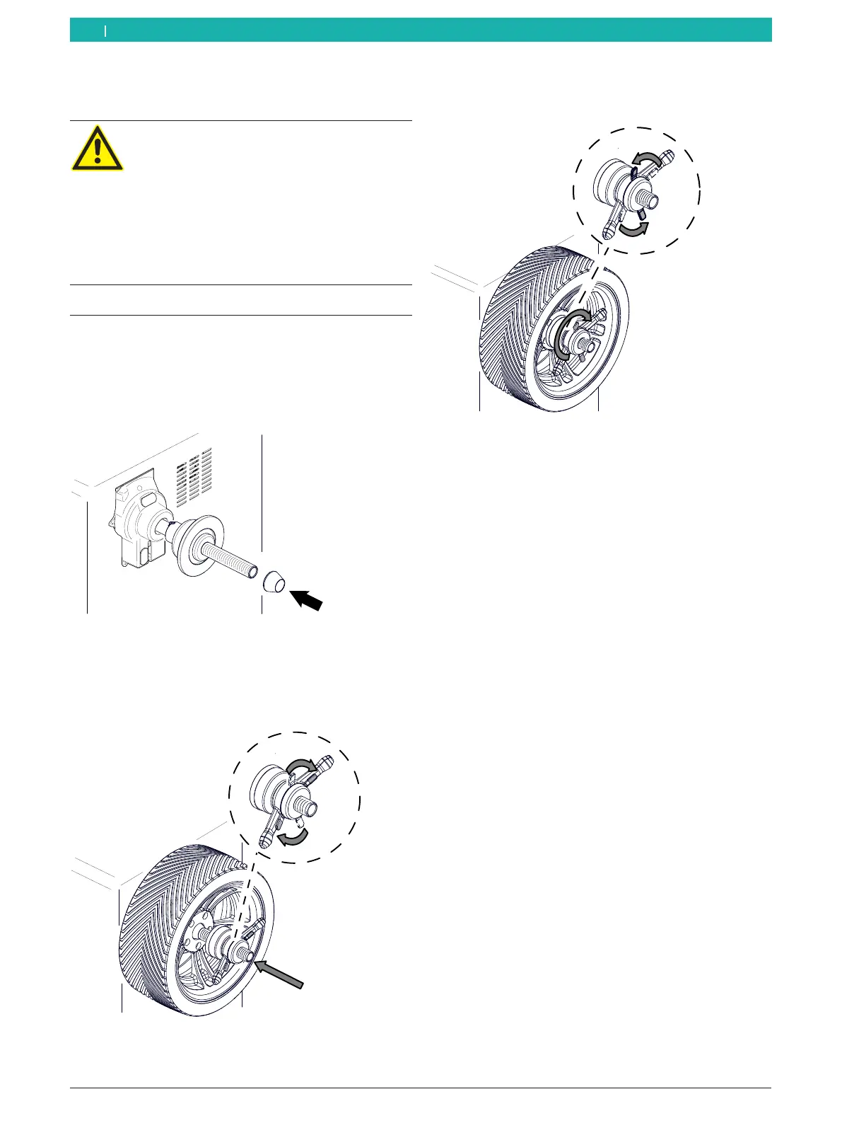
6. Release the lock, and turn the quick-locking ring
clockwise until the wheel is firmly held in place.
651127-72_BM
Fig. 56: Turning the quick-locking nut counterclockwise
" Wheel secured.
i For high-quality balancing, it is essential to tighten
the quick-locking nut securely.
! Make sure the wheel is held in place securely by the
clamping device.
6.1.2 Removing a wheel
1. Turn the quick-locking nut counterclockwise, and
release the wheel.
2. Disengage and remove the quick-locking nut.
3. Remove the wheel.
en