1 695 600 968 2019-01-28| Beissbarth GmbH
112 | MT ZERO 6 LCD | Imbalance minimization
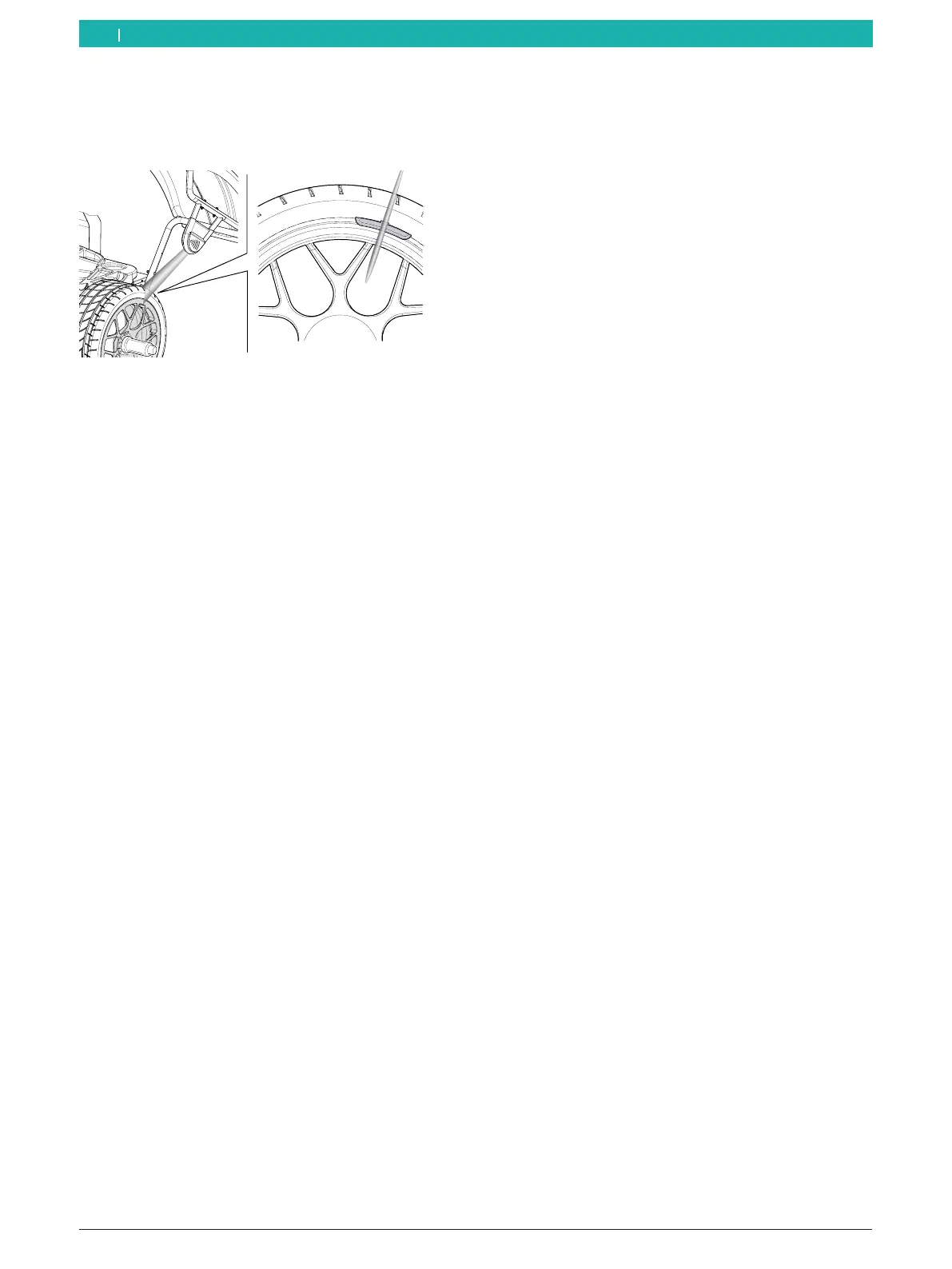
Outside rim flange (ALU3 1st balancing plane and
standard programs)
¶ A laser beam will be directed at the wheel. Attach the
balance weight at the center facing the indicator.
651127-81_BM
Fig. 99: Directing the laser beam at the rim flange
! Calibrate the device before its first use and
subsequently according to the maintenance
schedule.
! It is advisable to also calibrate the device whenever,
during the balancing process, a great number of
corrections is required for selecting and positioning
the balance weights.
i For the calibrating process, see the "External laser
indicator calibration" section.
i For attaching clip-on balance weights, see the
"Attaching clip-on balance weights" section.
9. Imbalance minimization
If the measured imbalance of the wheel is severe (e.g.
a static imbalance > 50g), it is advisable to perform
an "Imbalance minimization".
The program allows for the minimization of the total
imbalance by compensating the static imbalance of the
tire with that of the rim.
! Work as accurately as possible throughout the
procedure!
i Follow the instructions on the monitor.
i The matching program can be terminated by
pressing the <OPT> key.
i In the following description, automatic start is
active.
Phase 1
1. Press the <OPT> key to activate the function.
The first screen with instructions will be shown.
2. Close the wheel guard.
The measurement will start.
Phase 2
1. Turn the wheel until the tire valve is in the 12-o'clock
position.
2. Press the <MENU> key.
The reference position of the wheel will be saved
on the first start.
Phase 3
1. Mark the tire for reference (at the position of the
valve).
2. Remove the wheel from the flange.
i In order to rotate the tire on the rim, it may be
necessary to deflate it, unseat it (using a tire
changing machine) and to re-inflate it after rotating.
3. Rotate the tire on the rim by 180 degrees so that the
mark is across from the valve.
4. Re-assemble the wheel by fitting the tire correctly
on the rim and inflating it to the specified pressure.
! Do not change the positioning of the valve across
from the mark.
en