1 695 600 968 2019-01-28| Beissbarth GmbH
Operation | MT ZERO 6 LCD | 111
8.14 Attaching adhesive balance weights
by laser indicator
Some machine versions are equipped with a lighting
system and a laser indicator to determine the the
position for attaching the balance weight as quickly as
possible.
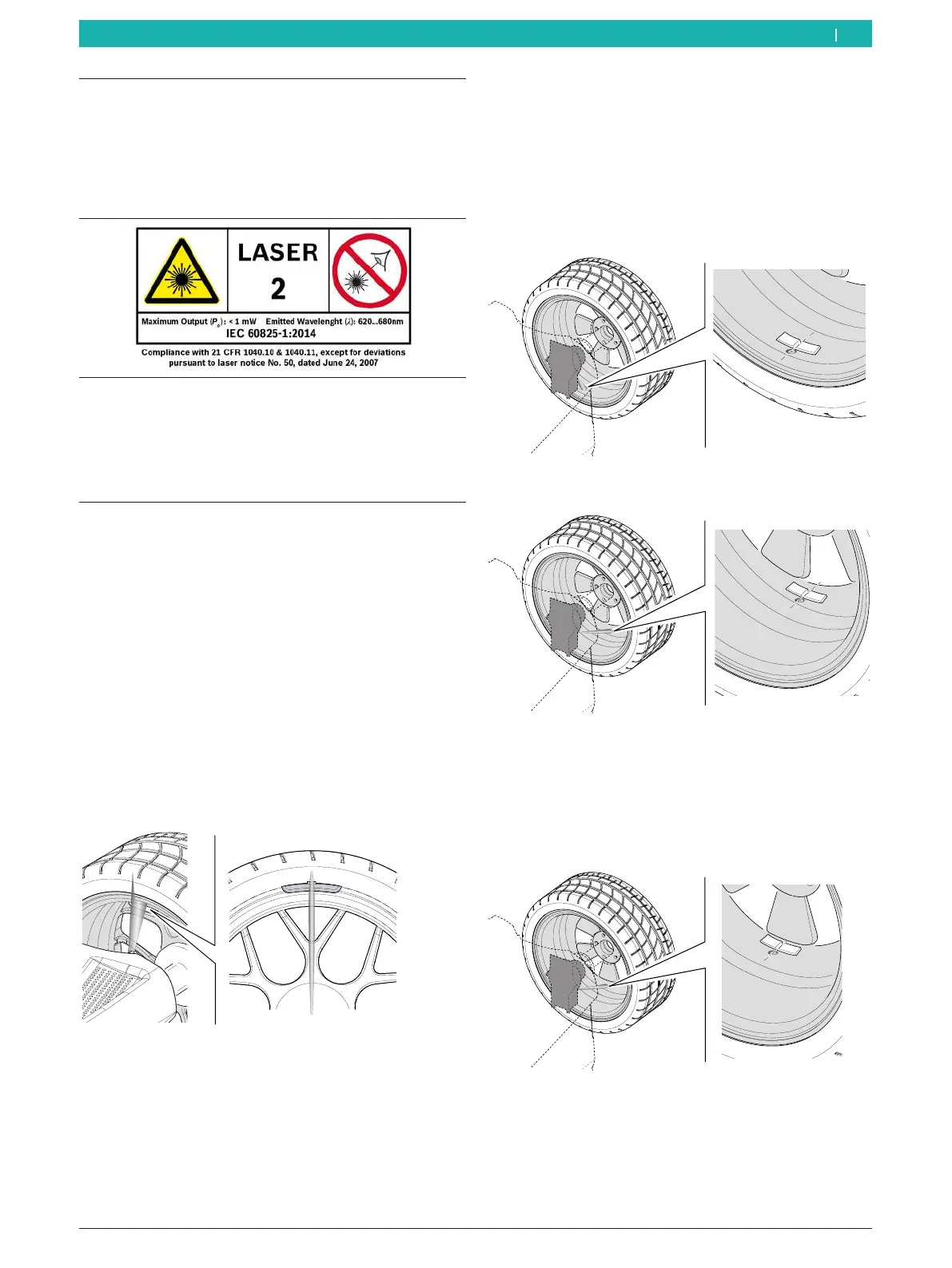
DANGER – LASER RADIATION!
Risk of severe eye injury by exposure of the eyes to the
laser beam (more than 0.2 seconds)
¶ Read the safety instructions in the "Safety standards
for the use of the position indicator laser beam"
section.
! The integrated laser indicator for attaching balance
weights will only be active if attachment by
electronic rim distance gauge is deactivated (see the
"Machine settings menu" section).
i The laser indicator will be activated once the wheel
is at rest in a balancing plane for attaching the
balance weight.
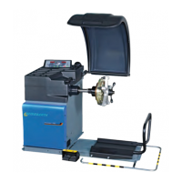
Inside rim flange (ALU3 1st balancing plane and
standard programs)
¶ A laser beam will be directed at the 12-o'clock
position of the wheel. Attach the balance weight at
the center facing the indicator.
651127-77_BM
Fig. 95: Laser beam projection on the rim flange
i For attaching clip-on balance weights, see the
"Attaching clip-on balance weights" section.
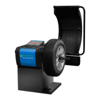
Attaching an adhesive balance weight in the rim well
(ALU3 2nd balancing plane and ALU2, PAX2)
¶ A laser beam will be directed at the 6-o'clock
position of the wheel. This is the exact location for
attaching the balance weight.
i Attach the edge of the balance weight at the center
facing the indicator.
651127-78_BM
Fig. 96: Laser beam projection on the first balancing plane for
ALU2
651127-79_BM
Fig. 97: Laser beam projection on the second balancing plane for
ALU2 and ALU3
i The laser beam projection on the second balancing
plane is used in the same way for the SPLIT
program. The only difference is that the balance
weight is attached behind a spoke.
651127-80_BM
Fig. 98: Laser beam projection in the SPLIT program
en