1 695 600 968 2019-01-28| Beissbarth GmbH
72 | MT ZERO 6 LCD | Symbols useden
1.2.3 Symbols on the product
Symbols Description Definition M
1
P
2
Direction of wheel
rotation
The wheel must turn in the direction of rotation
indicated (see sec. "Checking the direction of
rotation").
X X
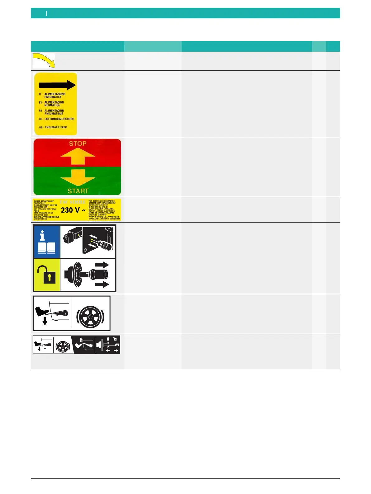
Compressed-air
supply
After the compressed-air supply has been
disconnected, the machine parts under pressure will
move to their resting positions automatically.
X
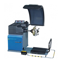
Start/stop balancing Adhesive label on the wheel protection casing.
Indicates the direction for starting and stopping the
rotation of the flange (wheel).
X X
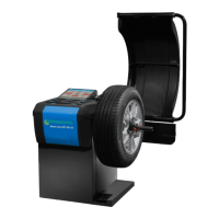
Intended voltage
supply
Information on the voltage set and safety warning X X
Releasing the
pneumatic flange
In case of a faulty compressed-air valve, proceed as
specified to remove the wheel.
X
STOP!
Using the pedal with
single function
Adhesive label on the body above the pedal.
Indicates the functions depending on how it is used.
R Pedal down:
lock shaft/wheel.
X
STOP!
Using the pedal with
double function
Adhesive label on the body above the pedal.
Indicates the functions depending on how it is used.
R Pedal up:
lock/release the pneumatic flange.
R Pedal down:
lock shaft/wheel.
X
1
M = MT ZERO 6 LCD AWx
2
P = MT ZERO 6 LCD AWxP