1 695 600 968 2019-01-28| Beissbarth GmbH
124 | MT ZERO 6 LCD | Maintenance
8. Use a quick-clamping ring to lock the calibration
plate in such a way that it is centered across from
the shaft.
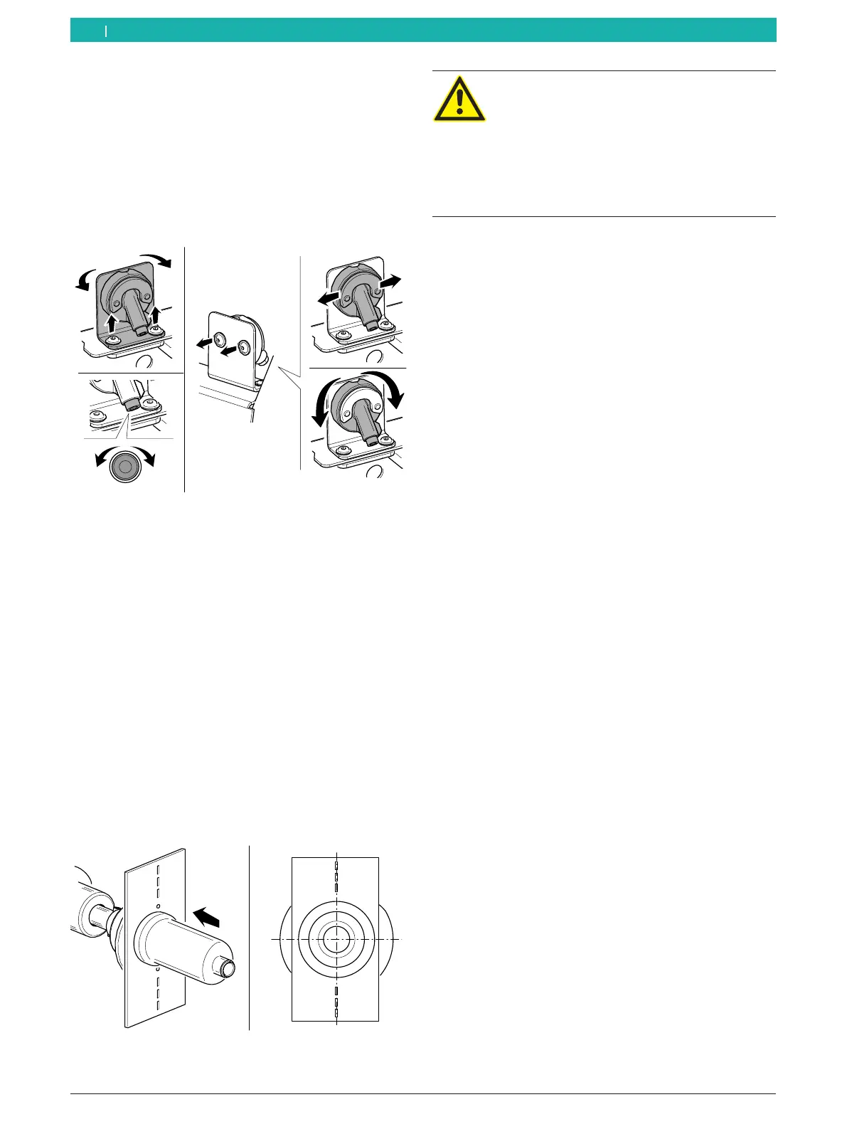
! Once the beam intersects with all the holes, the
calibration will be complete. If it does not, adjust
the position of the accessories in the places
pictured and make sure the position of the laser
beam is correct.
Fig. 110: Adjusting an external laser
" Calibration complete.
9. Remove the quick-clamping ring an the calibration
plate.
10. Install the cover of the sonar probe.
Pneumatic version
1. Push the pedal up.
The tie rod will move to the right.
2. Remove any dirt with a wire brush.
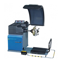
3. Place the calibration plate included in the scope of
delivery against the flange's surface.
4. Insert a small cone to center the calibration plate on
the flange shaft.
5. Slide the spacer plate onto the shaft, and press
it against the plate in such a way that the plate is
centered on the shaft.
6
651127-92_BM
Fig. 111: Attaching the calibration plate
WARNING – risk of crushing hands!
When clamping by pedal, there is a risk of
hand injury by crushing.
¶ Do not hold the spacer plate with
your hands within range of the locking
mechanisms.
¶ Do not place your hands between the
spacer plate and the calibration plate.
6. Push the pedal up.
The tie rod will move to the left.
The spacer plate will be pressed against the cali-
bration plate.
The calibration plate is now fixed in place.
7. Close the wheel guard.
The measurement will start. Wait until the pro-
cess is completed.
After the start, the laser beam will be activated.
i Some machine versions require the wheel to be
positioned manually according to the instructions
shown on the monitor.
i During the calibration of the device, the laser beam
will be directed at the holes in the calibration plate.
8. Lift the wheel guard fully.
i Release the spacer plate to be able to turn the
calibration plate.
9. Push the pedal up.
The tie rod will move to the right.
i Once the shaft rotates, the laser will be deactivated.
If necessary, reposition the shaft by hand.
en