1 695 600 968 2019-01-28| Beissbarth GmbH
Operation | MT ZERO 6 LCD | 105
4. Press the <START> key.
The wheel will automatically position itself on the
second balancing plane at low speed.
As soon as the correct position for attaching the
balance weight is reached, the reference line for
positioning is centered in the window at the right
and displayed in green. In addition, an audible
signal sounds to confirm that the position is cor-
rect.
The balance weight to be attached is displayed at
the upper right on the screen.
5. Select a balance weight (clip-on or adhesive) of the
required value.
6. Attach the balance weight according to the above
instructions.
i For machine versions with external laser indicators,
see the "Attaching adhesive balance weights by laser
indicator" section.
i The following happens when the <START> key is
pressed again:
$ The currently deactivated balancing plane is
displayed.
$ The wheel will automatically position itself on the
balancing plane selected.
i After the balance weights have been attached, the
imbalance must be measured again to check the
balance.
With manual positioning
i On some versions for certain markets, automatic
positioning is not available.
The following instructions apply even if that function
is deactivated.
! Before positioning, wait for the wheel to come to a
stop.
1. Lift the protective hood fully.
i The software suggests the closest lying balanced
plane and displays the corresponding weight value
on the screen.
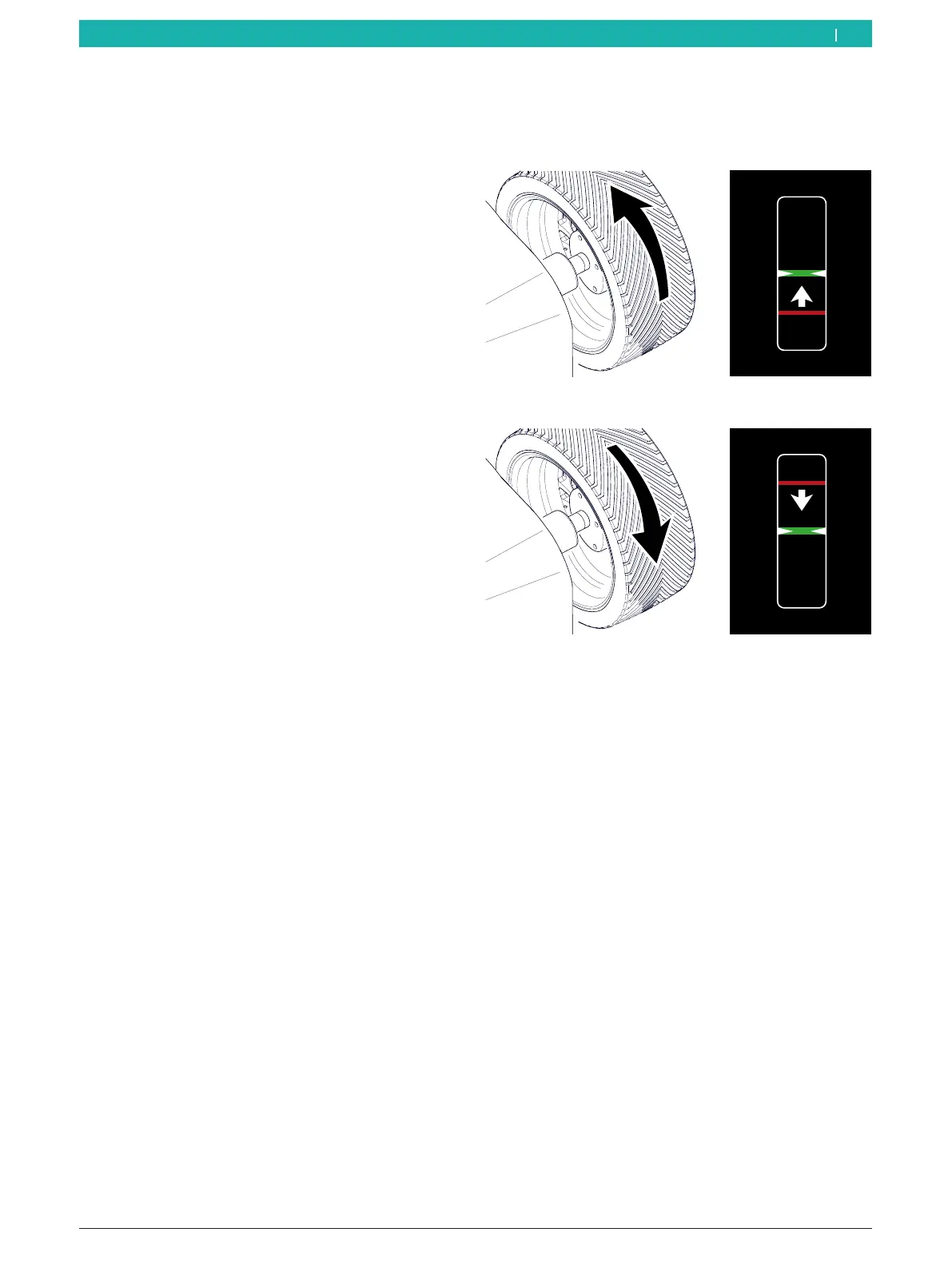
2. Rotate the wheel by hand until the reference line is
in the center of the window.
The line moves up when the wheel is rotated
clockwise.
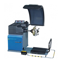
The line moves down when the wheel is rotated
counterclockwise.
3. Select a balance weight (clip-on or adhesive) of the
required value.
Rim flange (ALU3 1st balancing plane and standard
programs):
¶ Attach the clip-on balance weight and adhesive
balance weights at the highest vertical position on
the wheel (12 o'clock).
i Machine versions with an integrated laser indicator
will direct a laser beam at the 12-o'clock position of
the wheel. Position the balance weight at the center
facing the indicator (see the "Attaching adhesive
balance weights by laser indicator" section).
i For machine versions with external laser indicators,
see the "Attaching adhesive balance weights by laser
indicator" section.
i For attaching clip-on balance weights, see the
"Attaching the clip-on balance weights" section.
en