1 695 600 968 2019-01-28| Beissbarth GmbH
Operation | MT ZERO 6 LCD | 107
! Make sure the rotation of the wheel is not impaired
by tools or other objects.
2. Rotate wheel until one spoke is in the 12 o'clock
position and press the <SPLIT> key.
The position of the spoke is now saved.
The value of the number of spokes is hidden.
The windows for positioning the weights appear
on the screen.
The values required for the balance weights are
shown on the screen at the right next to the win-
dows for positioning.
i The value of the balance weight and the positioning
reference for attachment behind the second spoke
will remain deactivated during this initial phase.
i On machine versions with an integrated laser
indicator, it is possible to precisely indicate the
positioning of the spoke at the 6-o'clock position
instead of the 12-o'clock position after the function
has been activated.
i To close the balancing screen for the "split" function
and return to the basic screen, press the <SPLIT>
key.
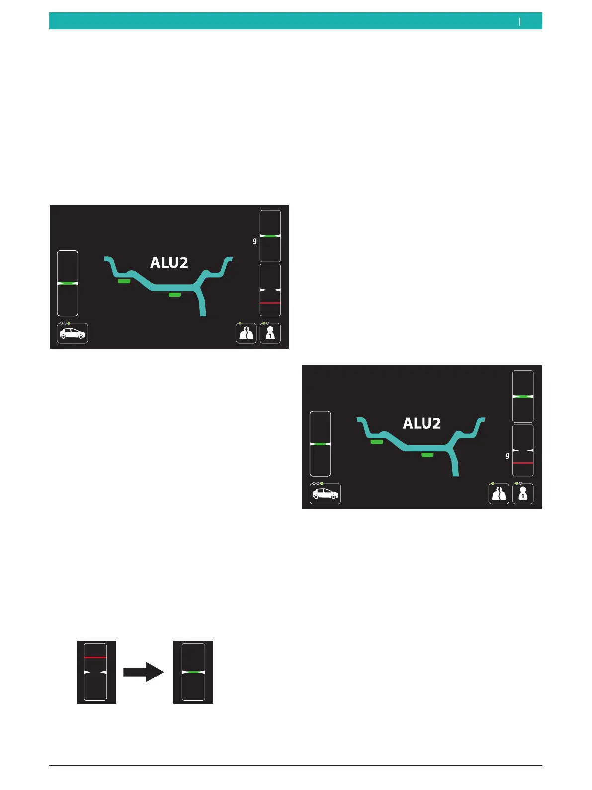
3. The wheel will automatically position itself in the
first position for attaching a balance weight behind a
spoke at low speed.
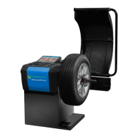
As soon as the correct position for attaching the
balance weight is reached, the reference line for
positioning is centered in the window at the top
and displayed in green.
The value of the balance weight is shown next to
the window.
i Some machine versions require the wheel to be
positioned manually according to the instructions
shown on the display.
4. Attach the adhesive balance weight of the correct
value using the electronic rim-distance gauge.
Attach the balance weight behind the first spoke.
i For attaching adhesive balance weights using
the integrated laser indicator, see the "Attaching
adhesive balance weights by laser indicator"
section. The laser indicator will only be active if the
attachment of the balance weight by electronic rim-
distance gauge is deactivated.
i For attaching adhesive balance weights, see the
"Attaching adhesive balance weights" section.
5. Press the <START> key.
The value of the balance weight to be attached in
the second position behind the spoke will be ac-
tivated.
The value of the balance weight to be attached in
the first position behind the spoke will be deac-
tivated.
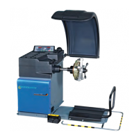
6. The wheel will automatically position itself in the
second position for attaching a balance weight
behind a spoke at low speed.
As soon as the correct position for attaching the
balance weight is reached, the reference line for
positioning is centered in the window at the bot-
tom and displayed in green.
The value of the balance weight is shown next to
the window.
i Some machine versions require the wheel to be
positioned manually according to the instructions
shown on the display.
en