1 695 600 968 2019-01-28| Beissbarth GmbH
120 | MT ZERO 6 LCD | Maintenance
" Flange calibration complete.
" The wheel imbalance has been set to a value of "0".
6. Press the <MENU> key.
The calibration options are presented again.
12.6.3 Calibrate the electronic rim-distance gauge
and the sonar probe.
i Follow the instructions on the monitor.
1. Call up the calibration menu.
The calibration options are presented.
2. Select the "Rim-distance gauge" menu item by
navigating through the options with the aid of the
<–> or <+> key.
3. Press the <MENU> key to confirm.
The calibration process will start.
i Calibration can be exited, at any time without saving
the settings by pressing the <STOP> key.
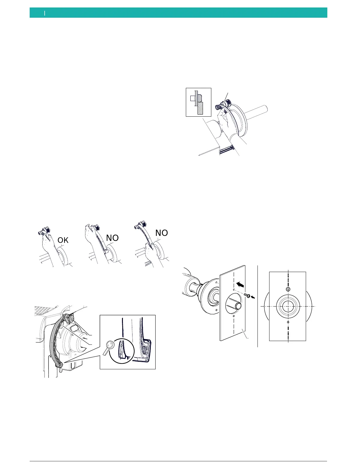
i When the rim data is calibrated, the handle of the
electronic rim-distance gauge must be held correctly
to avoid errors during balancing.
Fig. 100: Correct handling of the electronic rim-distance gauge
4. Set the electronic rim-distance gauge B to 0mm to
read off the distance.
1
2
651127-82_BM
Fig. 101: "0" distance position of the electronic rim-distance
gauge
1 Electronic rim-distance gauge
2 Mount for the electronic rim-distance gauge
5. Set the value "0" with the aid of the <–> or <+> key.
6. Press the <MENU> key to confirm.
The next screen is displayed.
7. Place the electronic rim-distance gauge in contact
with the inside of the flange.
8. Measure the distance and set the exact value that
has been read off.
9. Press the <MENU> key to confirm.
The next screen is displayed.
651113-02_BM
1
Fig. 102: Measuring the distance
1 Electronic rim-distance gauge
10. Move the electronic rim-distance gauge to its rest
position.
i The rest position is the position where the
electronic rim-distance gauge is resting fully in its
mount.
11. Attach the provided calibration plate to the threaded
hole of the flange.
12. Position the plate in the vertical 12-o'clock position.
1
12
6
651127-83_BM
Fig. 103: Attaching the calibration plate
1 Calibration plate
13. Close the wheel protection and confirm by pressing
<MENU>.
The next screen is displayed.
14. Open the wheel protection, place it in its home
position and confirm by pressing <MENU>.
The next screen is displayed.
en