Note
Note that the SFP connector on bintec RS120 and bintec RS120wu is not hotswap-
capable. Switch off the device before connecting an SFP module and restart the
device. You can only operate the Ethernet or the SFP connector for ETH5. When
changing between Ethernet and SFP operation, you must restart the device so that the
change can be completed correctly.
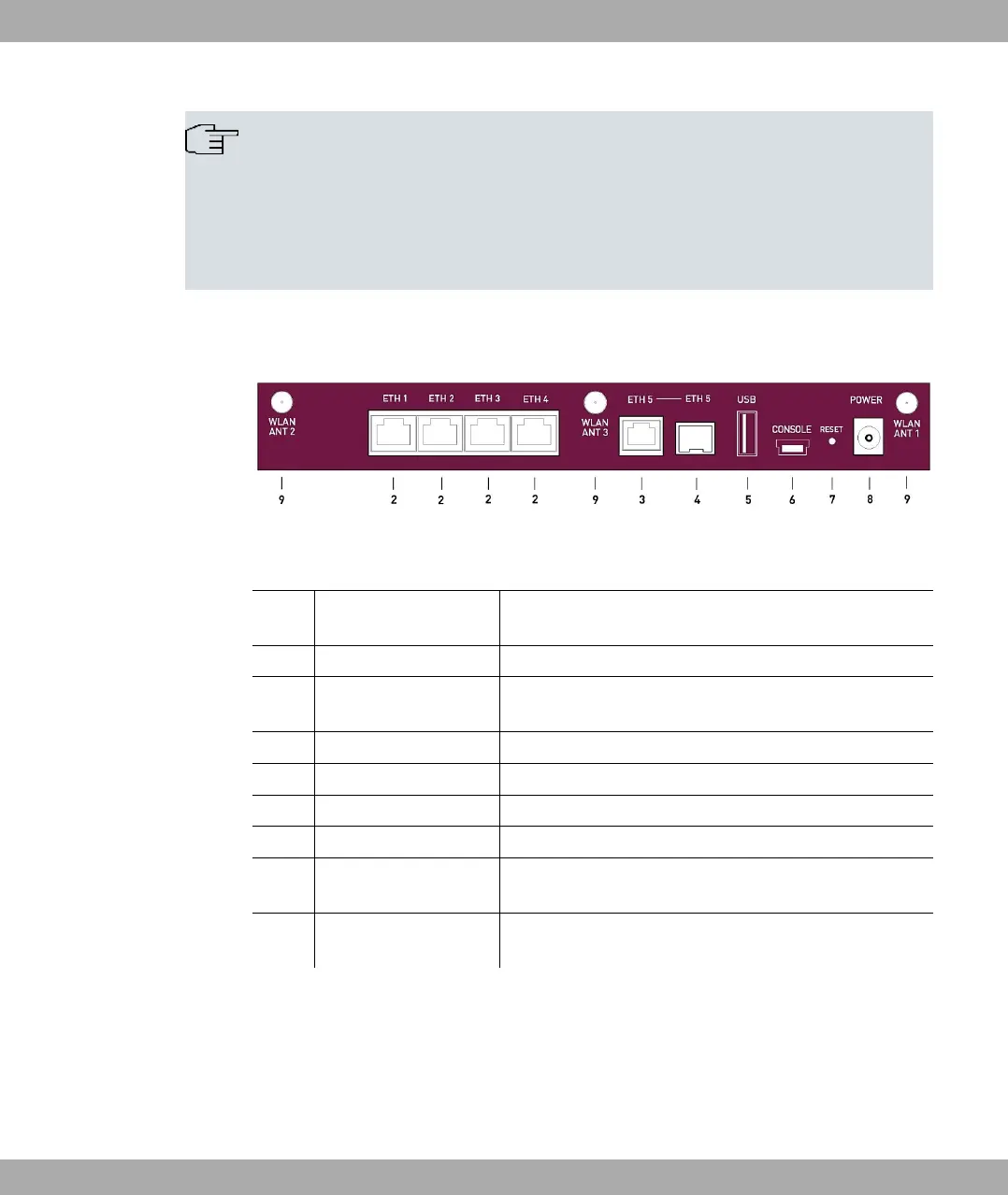
The connections are arranged as follows:
Fig. 7: bintec RS120wu rear panel
Rear panel
2 ETH1 / ETH2 / ETH3 /
ETH4 (yellow)
10/100/1000 Base-T Ethernet interface
3 ETH5 (white) 10/100/1000 Base-T Ethernet interface
4 ETH5 (white) SFP Slot for 10/100/1000 mbps Ethernet SFP modules
(optional)
5 USB USB connector
6 CONSOLE Serial interface
7 RESET Reset button
8 POWER Socket for plug-in power pack
9 WLAN ANT1 / ANT2 /
ANT3
RSMA connection (only bintec RS120wu )
without
Fig.
UMTS MAIN/AUX Connectors for UMTS antenna (only bintec RS120wu )
3.2.3 Antenna connectors
The devices bintec RS120wu have 3 connectors for the external WLAN antenna and in
addition 2 connectors for the external UMTS antenna (SMA connectors) on the sides. The
assignment of the two antenna connectors is shown in the following graphic:
3 Installation bintec elmeg GmbH
18 bintec RS Series