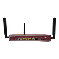
The interface is designed as a 5-pole mini USB socket.
Fig. 21: 5-pole mini USB socket
The pin assignment is as follows:
Pin assignment of the mini USB socket
Pin Position
1 Not used
2 TxD
3 RxD
4 Not used
5 GND
3.6.2 Ethernet interface
The devices have an Ethernet interface with integrated 4 port switch. This is used to con-
nect individual PCs or other switches.
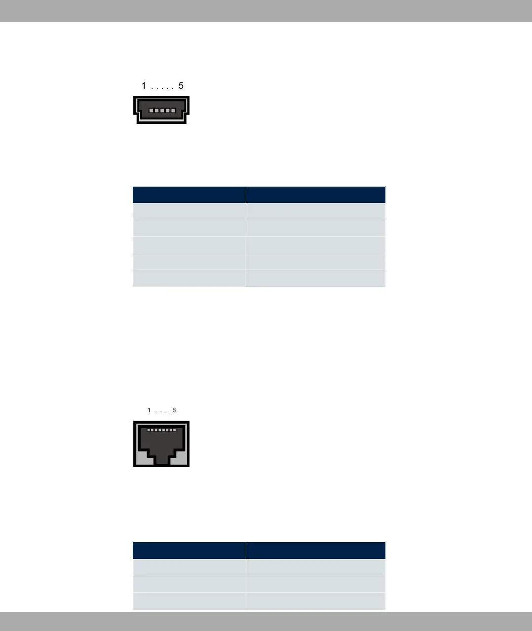
The connection is made via an RJ45 connector (yellow). The devices also have a fifth Eth-
ernet interface (white).
Fig. 22: 10/100/1000 Base-T Ethernet interface (RJ45 connector)
The pin assignment for the 10/100/1000 Base-T Ethernet interface (RJ45 connector) is as
follows:
RJ45 socket for LAN connection
Pin Position
1 Pair 0 +
2 Pair 0 -
3 Pair 1 +
3 Installation bintec elmeg GmbH
44 bintec RS Series