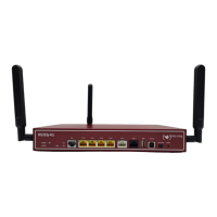
Fig. 4: bintec RS353j-4G rear panel
Rear pannel connections
9 POWER IEC C6 power connection and on/off switch
10 WLAN 1 / 2 Connections for the LTE/UMTS antenna (only bintec
RS353jw)
11 GPS Connection for the GPS antenna (only bintec
RS353j-4G)
12 LTE 1 - 2 Connections for the LTE/UMTS antenna (only bintec
RS353j-4G)
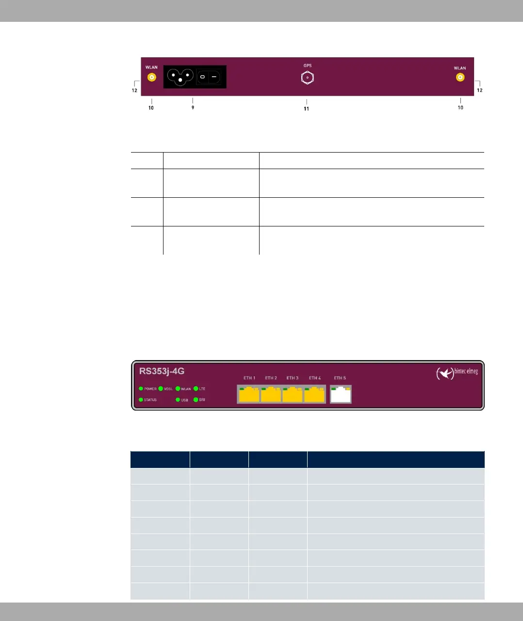
3.1.3 LEDs
The LEDs of your device provide information about specific activities and states of the
device.
The LEDs are arranged as follows:
Fig. 5: Arrangement of the LEDs
LED status display
LED Farbe Status Information
POWER green on Power supply is connected.
off No power supply.
STATUS green on The device has started.
green flashing During operation: An error has occurred.
off Normal operation.
VDSL green on VDSL connection established.
green flashing Data traffic via VDSL send / receive.
off No VDSL connection.
3 Installation bintec elmeg GmbH
10 bintec RS Series