ETH4 (yellow)
3 ETH5 (white) 10/100/1000 Base-T Ethernet interface
4 BRI (black) BRI interface
5 USB USB connector
6 CONSOLE Serial interface
7 RESET Reset button
8 POWER Socket for plug-in power pack
9 WLAN ANT1 / ANT2 /
ANT3
RSMA connection (only bintec RS232jw )
without
Fig.
UMTS MAIN/AUX Connectors for UMTS/LTE antenna (only bintec
RS232j-4G)
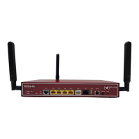
3.4.3 Antenna connectors
The devices bintec RS232jw have 3 connectors for the external WLAN antenna. The
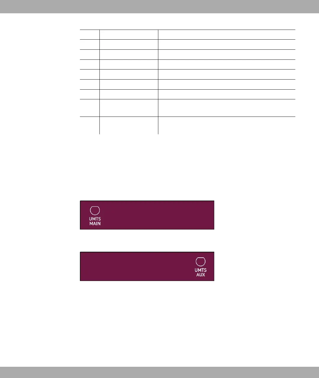
devices bintec RS232j-4G have two connectors for the external UMTS/LTE antenna (SMA
connectors). The assignment of the two antenna connectors is shown in the following
graphic:
Fig. 18: Antenna configuration of the bintec RS232j-4G
Fig. 19: Antenna configuration of the bintec RS232j-4G
3.4.4 LEDs
The device LEDs provide information on certain activities and statuses of the device.
The LEDs are arranged as follows:
bintec elmeg GmbH
3 Installation
bintec RS Series 37