S10/S12/S10A/S12A Patient Monitor User’s Manual
8-22
8.7.7. Entering ST Graphic Window
The steps to enter the ST Graphic window are as follows:
1. Select ECG parameter area, waveform area, ST parameter area or ST
waveform area to enter 【ECG】 menu.
2. Select 【ST】 submenu.
3. Select 【ST Graphic】 from the bottom of the menu.
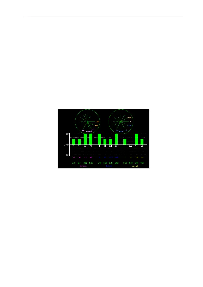
The following figure shows ST Graphic. The height of the bar represents the ST
value of the corresponding ST lead. The color of the bar indicates the ST alarm status:
green indicates that the ST value is within the normal range; Cyan, yellow and red
indicate that the ST value exceeds the alarm limit. The alarm color corresponds to the
level of ST alarm.
8.7.8. ST Setup
8.7.8.1. Setting ST Alarm
ST alarm is set as follows:
1. Select ECG parameter area, waveform area or ST parameter area to enter
【ECG】 menu.
2. Select 【ST】 submenu【Alarm】submenu.
3. Set the properties of ST alarm as required.
8.7.8.2. Showing ISO Point, J Point and ST Point Marks
The ISO point, J point and ST point position marks are not displayed by default on
the ST segment in the waveform area. To display these marks, the steps are as follows: