43
Series and Parallel Models
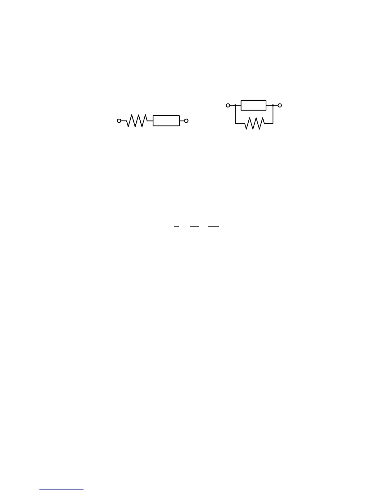
Components are modeled with one of the two following equivalent circuits:
Figure 15 - Series and Parallel Models
The impedance for the series model is:
The impedance for the parallel model is:
These circuit models are mathematically equivalent. The LCR meter measures an impedance,
which gives two independent numbers, the magnitude (|Z|) and phase (θ) of the impedance.
These are changed into rectangular components R and X, giving the real and imaginary part of
the impedance. These rectangular components can then be transformed into either a series or
parallel circuit of a pure resistance and pure reactance. These transformed circuits have exactly
the same impedance as the measured value, only at the measured frequency.
Choosing a Test Frequency
Test frequency can greatly affect the results of measurement reading, especially when
measuring inductors and capacitors. This section provides some recommendations and
suggestions to consider.
Capacitance
When measuring capacitance selecting, the right frequency is important in obtaining the
most accurate measurement results. Generally, a 1 kHz and above test frequency is used to
measure capacitors that are 0.01 µF or smaller. For capacitors that are 10 µF or larger, a
frequency of 1 kHz or lower can be used. Following this trend, high test frequencies are
best for testing very low capacitance components. For large capacitance components, low
www.GlobalTestSupply.com
Find Quality Products Online at: sales@GlobalTestSupply.com