22 EM-ABS-01 for ACU 03/12
Female connector X412
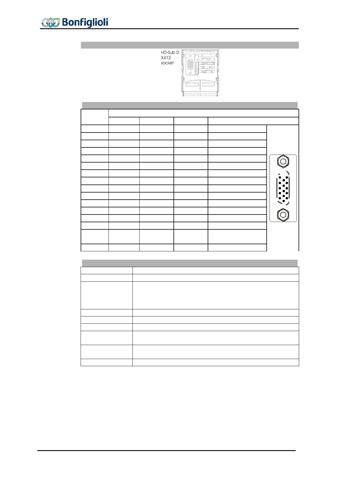
Encoder and PTC input X412 (female connector HD-Sub-D)
Contact
Function
Sin/Cos Hiperface EnDat 2.1 SSI
Housing PE PE PE PE
1 D- Clock- Clock-
2 D+ Clock+ Clock+
3 Cos- Cos- B- / Cos- (optionally B- / Cos-)
4 Cos+ Cos+ B+ / Cos+ (optionally B- / Cos-)
5 TM
PTC
– TM
PTC
– TM
PTC
– TM
PTC
–
6 V
Enc
V
Enc
V
Enc
V
Enc
7 R-
8 C- Data- Data- Data-
9 Sin- Sin- A- / Sin- (optionally A- / Sin-)
10 TM
PTC
+ TM
PTC
+ TM
PTC
+ TM
PTC
+
11 V
Enc
Sense
V
Enc
Sense
V
Enc
Sense
12 R+
13 C+ Data+ Data+ Data+
14
Sin+ Sin+ A+ / Sin+ (optionally A+ /
Sin+)
15 GND GND GND GND
Function and signal
Function Signal
Housing Shield connected with PE
+/A- Sin+/Sin-
B+/B- Cos+/Cos-
C+/C-
D+/D-
0.6 V … 1.2 Vss incremental signal
In the case of SSI encoders, the A+/A- and B+/B- tracks can be
used, as an option, for TTL [RS-422] or SinCos signals.
R+/R- DC 0.2 … 1.7 V analog signal
Clock+/Clock- Clock signal
Data+/Data- Data signal
TM
PTC
+
TM
PTC
–
Motor PTC
Enc
GND
Encoder supply (DC 5 … 12 V)
1)
, max. load capacity 2 W
EncS
Measuring line for monitoring of V
Enc
2)
V
ss
: peak-peak voltage
1)
The voltage value can be adjusted via parameter Supply voltage 1187. See chapter 8.4.4
Supply voltage”.
2)
oltage control via the measuring line can be activated, as an option, through parameter
ower Supply 1186. See chapter 8.4.3 “Power supply”.
1
5
6
10
11
15