03/12 EM-ABS-01 for ACU 85
8.1.3 Operation modes
The operation modes of the analog input characteristic enable application-related scal-
in
as a supplement to the characteristic points mentioned above. One of the fou
linear types of characteristic is selected for the si
nal adaptation for the analo
input
signal via parameter
Operation mode 562. If the points are not suited for the type o
characteristic selected, they are corrected internally.
Operation mode 562
Function
1 - bipolar
he analo
input si
nal is mapped onto the reference
value according to the points (X1/Y1) and (X2/Y2).
11 - unipolar With a negative parameter value of the points X1 or
X2, the latter are mapped to the reference value ze-
ro.
21 - unipolar 2-10V/4-20mA If the points X1 or X2 have been set with a negative
parameter value or less than 0%, the input characte-
ristic is mapped to the reference value 20%.
101 - bipolar abs. Ne
ative parameter values of the points Y1 or Y2 are
mapped as a positive reference value in the characte-
ristic.
Further information on the operation modes stated in the table can be found in the
following chapter "Examples“.
8.1.3.1 Examples
The analog input signal is mapped onto a reference value as a function of the charac-
teristic selected. The followin
examples show the operation modes for an analo
voltage signal. The parameter Minimum Frequency 418 has been set to the value
0.00 Hz. The characteristic point 100% for the Y axis corresponds to the parameter
Maximum Frequency 419 of 50.00 Hz in the examples.
Attention!
he various operation modes chan
e the input characteristic as a
func-tion of the characteristic points parameterized. In the following ex-
amples, the areas of the system of coordinates from which a characteristic
point is displaced are marked.
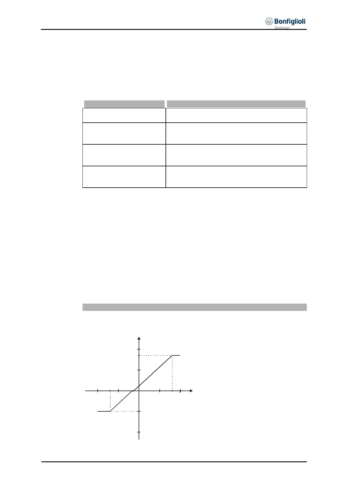
Operation mode "1 – bipolar"
In operation mode "1 – bipolar“, the characteristic of the analog input can be freely
set by stating two characteristic points.
(X2=80% / Y2=85%)
8V
Y
X
-25Hz
42.50Hz
(X1=-70% / Y1=-50%)
-7V
Point 1:
X1 = -70.00% · 10 V = -7.00 V
1 = -50.00% · 50.00 Hz = -25.00 Hz
Point 2:
X2 = 80.00% · 10 V = 8.00 V
2 = 85.00% · 50.00 Hz = 42.50 Hz
Tolerance band:
ΔX = 2.00% · 10 V = 0.20 V
he direction of rotation is chan
ed in this
example at an analog input signal of -1.44
, with a tolerance band of ±0.20 V.

 Loading...

