03/12 EM-ABS-01 for ACU 109
8.4.11.1 Example
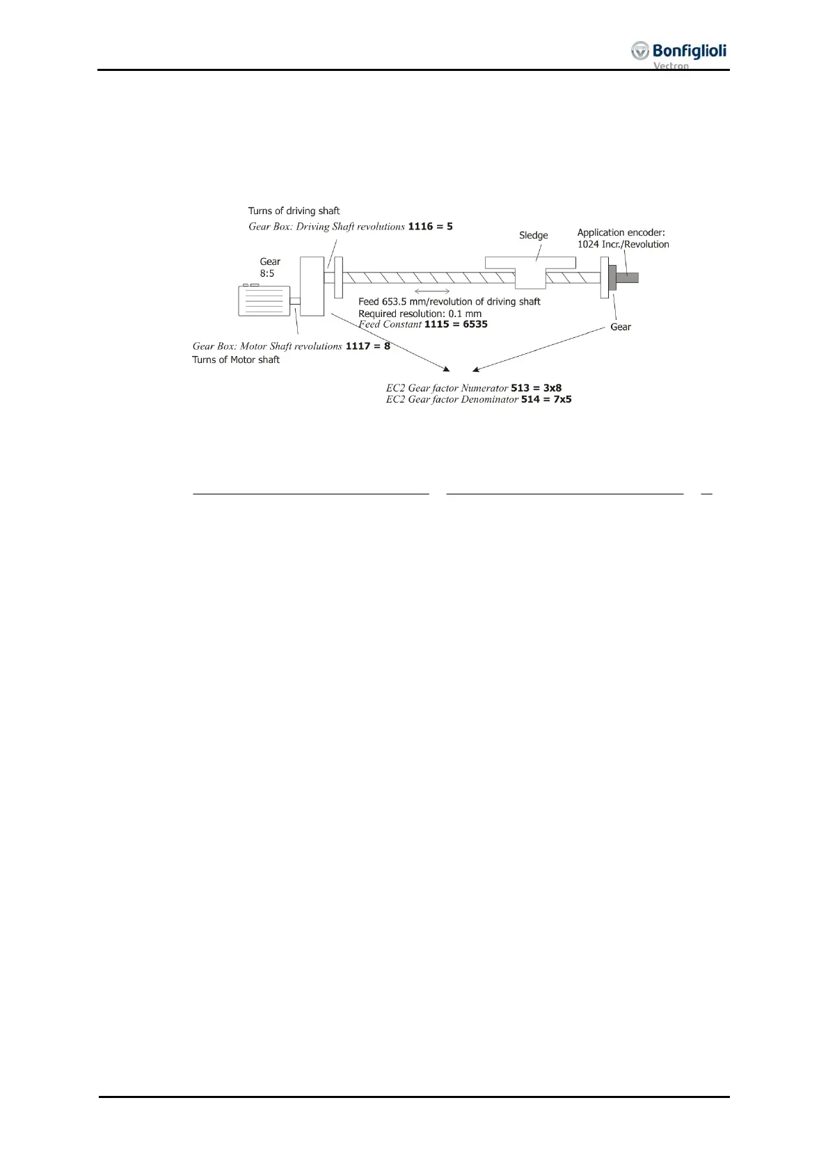
On a linear axis, the motor is flange-connected via a
ear (transmission ratio 8:1) and
the application connector is flange-connected via a second
ear (transmission ratio
3:1).
1 motor revolution = 1/8 turn on output side
= 1/8x3 encoder turn
3
8
shaft encoder EC2 the of sRevolution
shaftMotor the of sRevolution
==
514
513
rDenominato Factor Gear 2 EC
Numerator Factor Gear 2 EC
8.4.12 Instructions on speed-controlled configurations (“Not x40”)
In the case of speed-controlled configurations, an encoder is typically installed. Normal-
ly, this encoder is connected to the motor.
n internal format (referred to as 16/16) is used for speed control. The 16 less signifi-
cant bits represent the position an
le on a motor revolution, the 16 more si
nifican
bits represent the number of motor revolutions.
If absolute value encoders are used, the absolute value encoder notation is converted
to the internal notation. This is why, for proper function, the parameters of the abso-
lute value encoder must be entered in accordance with the data sheet. In the case o
other parameterizations, unwanted malfunction of the drive might occur.

 Loading...

